7.5
Shocks
7
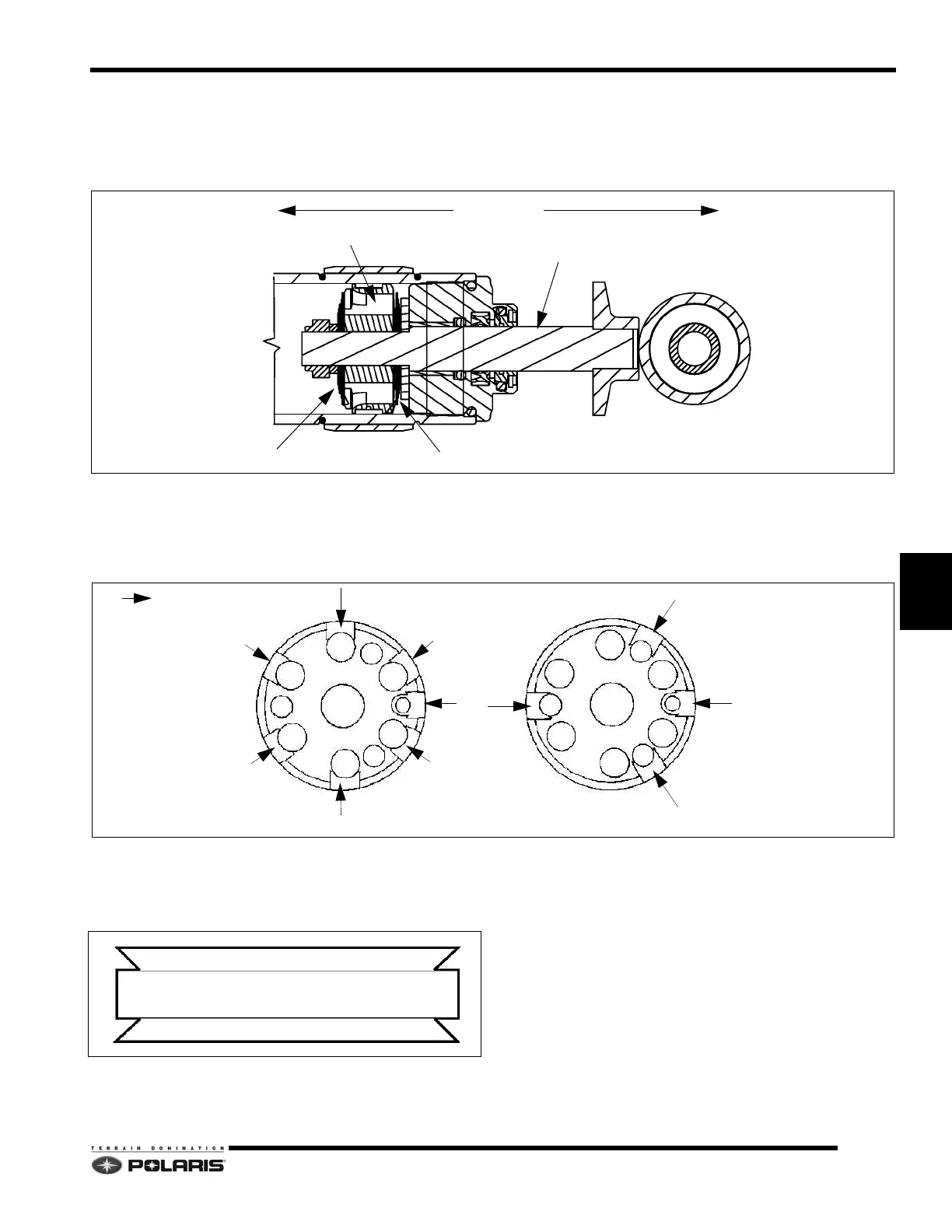
Valve Shim Arrangement
Shown below is an example of how valve stacks are
arranged.
NOTE: The rebound and compression valve stacks
will a
lways be positioned as shown in the illustration,
regardless of how the shock assembly is installed on
the snowmobile.
Piston Orientation
The face of the piston with the greater number of relief
ports will always face the rebound valve stack
NOTE: On some Walker Evans
™ shocks, the piston
is convex and color-coded.
Blue = COMPRESSION SIDE
Red = REBOUND SIDE.
PISTON
COMPRESSION VALVE STACK
REBOUND VALVE STACK
SHOCK ROD
FULLY EXTENDEDFULLY COMPRESSED SHOCK ROD
= Relief Port
Faces Rebound Stack
Faces Compression Stack
 Loading...


