10.36
Battery and Electrical Systems
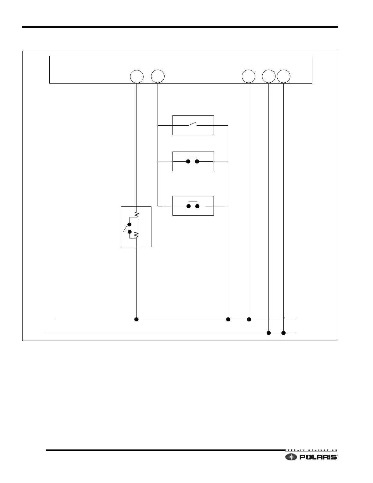
DC-CFI Throttle/Ignition Disable System
System Overview
A software stop is used to determine the position of the
throttle releas
e switch. The software stop system is
activated when the throttle release switch is closed
(closed throttle), but the TPS (throttle plate position) is still
above idle. When this occurs, the ECU will determine the
throttle cable is “stuck” and disable the ignition system.
To test the throttle lever, measure the resistance with the
le
ver pushed/closed and compare results to those in
illustration.
Always verify the throttle lever freeplay is set to
s
pecification.
A hardware stop system is a direct ignition kill
system.
That is, whenever the operator turns the key to off, pulls
the tether, or pushes the safety slap switch down, the
ignition system is immediately killed.
SENSOR GROUND
BLK/BLU
DC--CFI ECU CNA CONNECTOR
IGNITION SWITCH
(SWITCH CLOSED WHEN KEY
TURNED TO OFF)
7
TETHER SWITCH
(CLOSED WHEN TETHER
REMOVED)
OPTIONAL
25
SAFETY SLAP SWITCH
(PUSHED = CLOSED)
THROTTLE LEVER SWITCH
2148 OHMS = SWITCH CLOSED/LEVER REL.
6788 OHMS = SWITCH OPEN/LEVER PUSHED
CHASSIS / ENGINE
GROUND
BRN
16
BLK/RED
9
BLACK
15
2148
4640
 Loading...


