10.9
Battery and Electrical Systems
10
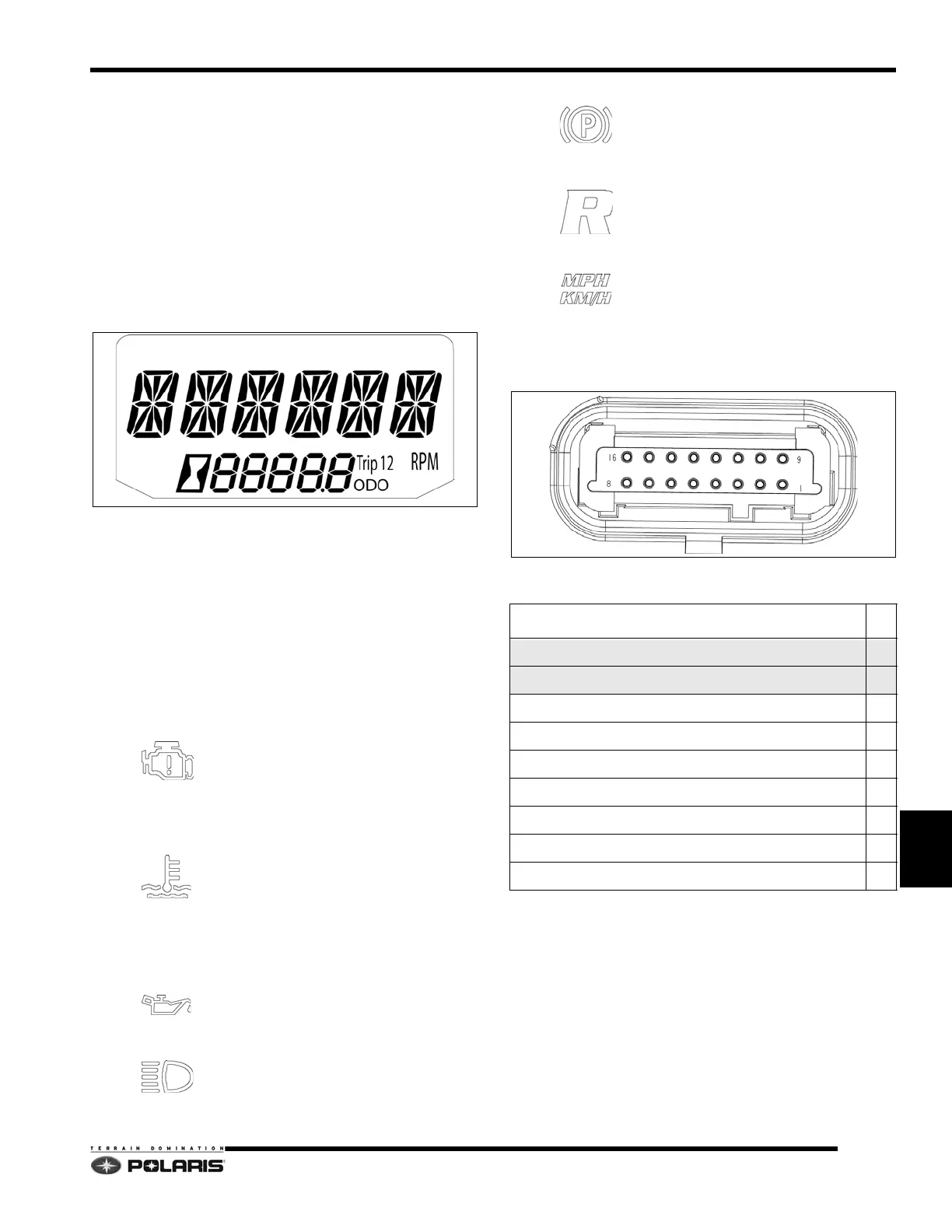
Rider Information Display
The rider information display is located in the instrument
cluster. All segments will illuminate for approximately one
second at start-up.
Use the MODE button on the cluster or the left hand
co
ntrol to toggle between options. To clear a trip meter,
toggle to the meter (1 or 2), and press and hold the MODE
button on the cluster or left hand control.
NOTE: If the instrument cluster fails to illuminate, an
ov
er-voltage condition may have occurred forcing the
instrument cluster to power down.
• RPM (T
achometer) - LCD display of engine RPM
• Odomet
er / Engine Hours - LCD display of total
vehicle miles/km or total accumulated engine
hours
• T
rip 1 / Trip 2 - LCD display of trip meters
Indicator Lamps
The indicator lamp panel displays the indicator and
warning lamps.
•Check Engine MIL - Illu
minated when
the ECU has detected a Diagnostic
T
rouble Code (DTC) within the engine
management system. Icon will flash
when DTC display mode is active.
•Engine Temperature Indicator - L
ED
icon will illuminate when the ECU
de
termines the engine is overheating.
The icon will flash to indicate the
engine is overheating. The icon will
stay lit and not flash if a severe
overheating condition exists.
•Low Oil Level Indicator - Ic
on will
illuminate when the oil level in the oil
t
ank becomes too low.
•High Beam Indicator - LED w
ill
illuminate when the high beam
h
eadlamps are active.
•Parking Brake Indicator - Ic
on will
illuminate whenever the brake lever is
p
ulled or when the parking brake is
engaged.
•Reverse Indicator -
Icon will
illuminate and flash whenever
PERC
reverse mode button is pushed on the
LH control.
•MPH / KM/H - Un
its of measure gauge
is set to
Instrument Cluster Pinouts
NOTE: CAN wires are twisted together and must
remain twisted to prevent interference.
Connector Pinouts
FUNCTION PIN
CAN High - YELLOW 1
CAN Low - GREEN 2
DC Gauge Voltage (VDC) - RED/WHT 3
DC Gauge Voltage (VDC) - RED/WHT 4
Ground - BRN/WHT 5
High Beam Switch - YEL/RED 8
Fuel Level - VT/WHT 11
LH Set Switch - WHT/BLK 12
LH Mode Switch - WHT/RED 13
 Loading...


