Home
Polaris
Snowmobiles
800 RMK ASSAULT 2011
Polaris 800 RMK ASSAULT 2011 User Manual
4
of 1
of 1 rating
512 pages
Give review
Manual
Specs
To Next Page
To Next Page
To Previous Page
To Previous Page
Loading...
5.15
Final Drive/Brake System
5
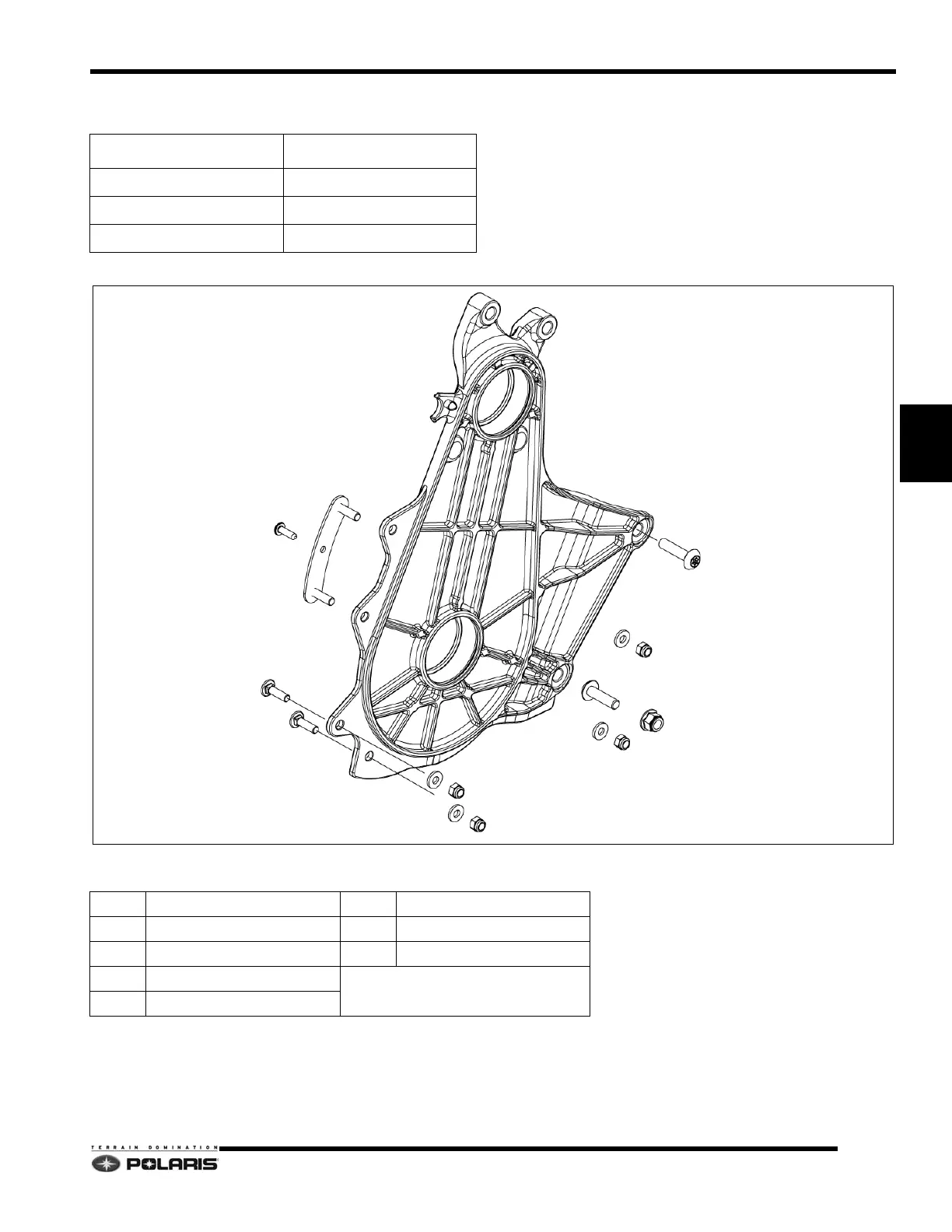
QuickDrive™ Backer
Plate Assembly View
COMPONENT
TORQUE
Screw (M8 1.25x35)
26 ft-lbs (35 Nm)
Screw (M8 1.25x30)
26 ft-lbs (35 Nm)
Screws (M6 1.0x
22)
9 ft-lbs (12 Nm
)
QuickDrive™ Backer
Plate Assembly
1.
Backer Plate
6.
W
ashers
2.
St
u
d
P
l
a
t
e
7.
Nuts (M6)
3.
Screw (M8 1.25x35)
8.
Nut (M8)
4.
Screw (M8 1.25x30)
5.
Screws (M
6 1.0x22)
1
2
3
4
5
6
6
6
7
7
7
8
234
236
Table of Contents
Table of Contents
1
2011 600 Rush
4
Chapter 1
4
2011 800 Rush
6
2011 800 Switchback Assault
8
2012 600 Rush
16
2012 800 Rush
18
2012 600 Switchback
22
2012 800 Switchback
24
2012 Switchback Assault
26
2012 800 Pro Rmk 155/163
38
2013 600 Indy/Indy Sp
40
2013 600 Rush
42
2013 600 Switchback
48
2013 800 Switchback
50
2013 Switchback Assault
52
2013 600 Rmk 144
54
2013 600 Rmk 155
56
2013 600 Pro Rmk 155
58
2013 800 Pro Rmk 155/163
64
Snowmobile Number Designations
66
Vehicle Identification Number
66
Vin Number Designation
66
Tunnel Decal
67
Publication Part Numbers
68
2010 Publications
68
Special Tools
70
General Reference
71
Standard Bolt Torque Specification
71
Metric Bolt Torque Specification
71
Gasoline Volatility
72
Fuel / Oil Premix Ratios
72
Fuel Recommendations
72
Sae Tap Drill Sizes
73
Metric Tap Drill Sizes
73
Decimal Equivalents
73
Chapter 2 Maintenance
75
Periodic Maintenance
77
Maintenance Products
79
Engine Oils / Lubricants / Misc
79
Break-In Procedures
80
Engine Break-In Procedure
80
Fuel/Oil Premix Ratio
80
Drive Belt Break-In Procedure
80
Engine Maintenance
80
Variable Exhaust Valve Cleaning
80
Spark Plugs
82
Spark Plug Caps/Spark Plug Terminals
83
Spark Plug Wire Maintenance/Routing
83
Surge Tank
84
Recommended Coolant
84
Cooling System Bleeding
84
Engine Mount Bolt Re-Torque
85
Oil Pump Adjustment
86
Oil Pump Bleeding
87
Oil Injection Hose Priming
87
Oil Tank/Clutch Cover Service
88
Oil Filter Service
89
Oil Supply Hose Routing/Panduit Strap
90
Pvt System
91
Belt Deflection Inspection
91
Team/P2 Deflection Adjustment
91
Torque Limiter
91
Clutch Alignment/Offset
92
Offset/Float Adjustment
92
Adjusting Engine Mount Bolts/Engine Alignment
93
Fuel/Intake System
94
Fuel Filter - DC-Cfi-4 Models
94
Fuel Filter - DC-Cfi-2 Models
94
Fuel Hose Inspection
96
Fuel Tank Vent System
96
Fuel Tank Vent Hose Routing
97
Air Box/Pre-Filters
97
Air Box Servicing
98
Chassis
99
Door/Hood Removal and Installation
99
Chain Case Oil Level Check
101
Chain Case Oil Replacement
101
Drive Chain Tension Adjustment
101
Chain Case Fastener Re-Torque
102
Quickdrive™ Low Inertia System
102
Brake System Maintenance
103
Brake Lever Travel
103
Brake Fluid
103
Brake Pad Replacement
103
Throttle Cable Adjustment
103
Throttle Lever Free-Play
103
Throttle Cable Routing
104
Steering / Suspension Maintenance
104
Handlebars
104
Adjustable Riser
105
Ski/Ski Skag Fasteners
105
Track Tension
106
Track Alignment
107
Suspension Pivots/Lubrication
107
Suspension Lubrication
108
Electrical Systems
109
Headlight Bulb Replacement
109
Tail Lamp Replacement
109
Off-Season Storage
110
Chassis and Hood
110
Clutch and Drive System
110
Controls and Linkage
110
Electrical Connections
110
Carburetor/Throttle Body
110
Fuel System
110
Corrosion
110
Shocks
110
Battery
110
Chapter 3 Engine/Cooling/Exhaust
111
Engine Specifications
113
Fastener Torque Guide
113
Component Torque Sequences
114
Engine Service Specifications - All Engines
115
Engine Specifications
115
Vehicle/Engine Matrix
116
Engine Inspections
117
Cylinder Head Inspection
117
Cylinder Measurement
118
Piston Inspection
119
Piston Ring Installed Gap
119
Reed Valve Inspection
120
Bearing Fit
120
Crankshaft Runout Inspection
121
Main Bearing
121
Connecting Rod Lower Bearing
121
Piston Needle Bearing
122
Crankshaft Index
123
Checking Crankshaft Index
123
Cylinder Honing
124
Honing Tools
124
Honing Procedure
124
Cleaning the Cylinder after Honing
124
Crankshaft Truing
125
Special Tools
117
Special Tools - Engine
117
Engine Mounting Systems
126
2011 800 Engine Mounting
128
Engine Mount Bolt Service Replacement Kit
130
Engine Mount Screw Installation
130
Recoil Assembly
131
Rope Removal and Installation
131
Engine Component Assemblies
132
600 Cylinder Head/Cylinders/Pistons
132
600/800 Recoil/Stator Assembly
134
600 Crankcase/Crankshaft Assembly
136
600 DC-CFI-2 Crankshaft Identification
137
DC-Cfi-2 Cylinder Head/Cylinder/Pistons
138
Cylinder Head/Cylinder/Piston Notes
139
DC-Cfi-2 Cylinder Head/Cylinder/Pistons Disassembly/Assembly .3.29
139
800 DC-CFI-2 Crankcase/Crankshaft
140
800 DC-CFI-2 Crankshaft Identification
141
600/800 DC-Cfi Water and Oil Pump Assembly
142
Oil Hose Routing
144
Engine Removal
145
Engine Installation
148
Cooling System
151
Thermostat Replacement
151
Thermostat Orientation
151
800 Thermostats
151
2010 600 Rush Cooling System
152
2012-2013 600 Rush/Switchback Cooling System
155
Switchback Assault/Base Rmk Cooling System
157
Pro Rmk/Rmk Assault Cooling System
158
600 INDY Cooling System
159
Front Heat Exchanger Service
160
Exhaust Systems
161
Pro-Ride DC-Cfi-4 Exhaust System
161
Pro-Ride DC-Cfi-2 Exhaust System
162
Variable Exhaust System (Ves)-Threaded Valve
163
Variable Exhaust System (Ves)-Threaded Stud
164
Chapter 4 Cleanfire Fuel Injection
165
Service Warnings and Precautions
167
Engine Protection Features
168
Engine Temperature Rpm Limit
168
Engine Overheating Troubleshooting
168
Detonation Protection (Det)/Rpm Limit
169
Det Troubleshooting
169
Cleanfire Fuel Injection
169
System Overview
170
Fuel Select Feature
171
Resistor Fuel Selector Plugs
171
Dual Resistor Fuel Selector Plug
171
Instrument Cluster Fuel Selector
172
Diagnostic Trouble Codes (Dtcs)
173
Diagnostic Trouble Code (Dtc) Troubleshooting
175
Analog/Digital IC Error Code Display
176
Digital IC Error Code Display
176
Ecu 34 Pin Connector (Chassis)
177
Ecu 26 Pin Connector (Engine)
178
Exhaust Temperature Sensor
179
Temperature / Air Pressure Sensor (Tmap)
179
Crankshaft Position Sensors (Cps)
179
Crankshaft Position Sensor Air Gaps
179
Exhaust Valve Solenoid
180
Ignition Coils
180
Engine Coolant Temperature Sensor
181
Knock (Det) Sensor
181
Throttle Body Removal
181
DC-Cfi-4 Fuel Injectors/Fuel Rail
182
Fuel Injectors
182
Fuel Rail Bleeding / Pressure Testing
182
Disconnect Fittings
183
Fuel Rail/Injector Removal/Installation
183
Fuel System Assembly
186
DC-Cfi-2 Fuel Injectors/Fuel Rail
187
Fuel Injectors/Assembly
187
Fuel Rail Bleeding / Pressure Testing
188
Disconnect Fittings
189
Quick Disconnect Fittings
189
Fuel Rail Microdampers
190
Fuel Rail/Injector Removal and Installation
191
Fuel Tank/Pump Service
192
2010 Fuel Tank/Pump Assembly
192
2011-2013 Rush/Switchback Fuel Tank/Pump Assembly
193
2011-2013 Indy/Switchback Assault/Rmk Fuel Tank/Pump Assembly
194
Fuel Tank Service
195
Fuel Pump Service
195
Fuel Pump/Level Sender Test Specifications
196
Fuel Tank Pressure Test
196
Rush/Switchback Fuel Pump Pickup Orientation
197
Digital Wrench® Diagnostic Software
198
Digital Wrench® Diagnostic Software Overview
198
Special Tools
198
Diagnostic Software Version
198
Ecu Replacement
198
Guided Diagnostics Available
198
Digital Wrench® Communication Errors
199
Digital Wrench® - Diagnostic / Power Connectors
199
Digital Wrench® Serial Number Location
200
Digital Wrench® Version and Update ID
200
Digital Wrench® Updates
200
Digital Wrench® Feature Map
202
Updating Digital Wrench
203
Version Identification
204
Special Tests Menu
204
Vehicle History Information
204
Service Report
204
Ecu Replacement
205
Engine Controller Reprogramming (Reflash)
205
Digital Wrench® Data Grid Screenshots
208
Throttle Position Sensor
209
Throttle Position Sensor (Tps) Overview
209
Tps Tests
210
Tps Set Procedure Menu
211
Throttle Position Sensor (Tps) Wire Harness Routing
215
Variable Exhaust System (Ves)
215
Overview
215
Electronic Reverse (Perc)
216
Overview
216
Operation
216
Forward Operation
216
Altitude Setting
217
Important Notes
217
Troubleshooting
218
Engine will Not Start
218
Engine Starts - Won't Idle/Stalls
218
Poor Performance
218
DC-Cfi Troubleshooting Flowchart
219
Detonation Limit Troubleshooting Flowchart
220
Chapter 5 Final Drive/Brake System
221
Track Stud Specifications
222
Drive Gears/Chains
223
Drive Gears
223
Drive Chains
223
Gear Ratio Speed Chart
224
7.53 CD Chaincase Speed Chart
224
Chaincase
225
Specifications/Torque Guide
225
Chaincase Cover Torque Pattern
225
Brake Caliper Types
225
Full Assembly View
226
Chaincase Disassembly
227
Chaincase Assembly
228
Mounting Assembly View
230
Non-Bonded Chaincase Removal/Installation
230
Bonded Chaincase Removal/Installation
231
Quickdrive™ Low Inertia Drive System
232
Specifications/Torque Guide
232
Assembly View
232
Quickdrive ™Drive Belt / Sprocket Removal
233
Quickdrive ™Drive Belt / Sprocket Installation
234
Quickdrive™ Backer Plate Assembly View
235
Quickdrive™ Backer Plate Removal
236
Quickdrive™ Backer Plate Installation
237
Driveshaft/Jackshaft
238
Specifications/Torque Guide
238
Assembly View
238
Jackshaft Removal
239
Jackshaft Installation
239
Driveshaft Removal
239
Driveshaft Installation
239
Brake System
240
General Guidelines
240
Overview
241
Compensating Port
241
Brake Fluid Replacement & Bleeding
242
Combined Master Cylinder/Lever Service
243
Cyclone Master Cylinder/Lever Service
243
Brake Line Replacement
244
Brake Hose Routing
245
Combined MC Brake Light Switch Replacement
245
Phantom Brake Caliper Removal
246
Phantom Brake Caliper Installation
246
Phantom Brake Caliper Piston and Seal Replacement
246
Phantom Brake Pad Replacement
247
Phantom Lite Brake Caliper Bracket/Seal/Piston Service
248
Phantom Lite Brake Pad Replacement
250
Brake Disc Replacement
251
Chapter 6 Pvt System
253
Pvt System
254
Special Tools
256
Drive Clutch Springs
257
Drive Clutch Weights
258
Spring Free Length
258
Perc Team Lwt Driven Helixes (24 Fin)
259
Team Ramp Angles
259
Team Driven Springs
260
Polaris P2 Driven Non-Tabbed Springs
261
Polaris P2 Tabbed Driven Springs
261
P2 Helix Angles
262
Polaris P2 Driven Helixes
262
Belt Inspection
263
Drive Belts
263
Belt Wear / Burn Diagnostics
264
Adjusting Belt Deflection - Team Driven Clutch
265
Drive Belt Installation - Team Driven
265
Drive Belt Removal - Team Driven
265
Adjusting Belt Deflection - Spa P2
266
Drive Belt Installation - Spa P2
266
Drive Belt Removal - Spa P2
266
Pvt System Adjustments
267
Clutch Alignment/Offset
267
Offset/Float Adjustment
267
Adjusting Engine Mount Bolts/Engine Alignment
268
Drive Clutch
269
Identification
269
Drive Clutch Removal
269
Drive Clutch Disassembly
270
Roller Removal
271
Roller Installation
271
Spider Button Installation
271
Bushing/Insert Replacement
272
Moveable Sheave Bushing/Insert Removal and Installation
272
Cover Bushing
272
Clutch Assembly
273
Belt-To-Sheave Clearance Adjustment
273
Spider Indexing
274
Drive Clutch Installation
275
Driven Clutch
275
Driven Clutch Removal
275
Driven Clutch Installation
275
Team Lwt Components
276
Polaris Spa-P2 Driven Clutch Components
277
Pvt System Troubleshooting
278
Drive Belt
278
Drive Clutch
278
Driven Clutch
278
Chapter 7 Shocks
279
Special Tools
280
Valve Shims
281
Fox™ Shock Valve Part Numbers
281
Walker Evans™ Shock 3/8" Valve Part Numbers
282
Valve Shim Arrangement
283
Piston Orientation
283
Specifications
284
2011 Pro-Ride Model Shock Specifications
287
2012 Pro-Ride Model Shock Specifications
290
Shock Maintenance
296
Walker Evans™ Coil-Over Piggyback Shock
296
Fox™ Ifp Monotube Shock Disassembly
300
Fox™ Ifp Monotube Shock Assembly
301
Walker Evans™ Ifp Monotube Shock
304
Fox™ Ps-5 Assembly View
306
Fox™ Ps-5 Disassembly
307
Fox™ Ps-5 Assembly
310
Fox™ Zero Pro Assembly View
313
Fox™ Zero Pro Shock Disassembly
314
Fox™ Zero Pro Shock Assembly
317
Chapter 8 Steering and Suspensions
321
Inspection
323
Overview / Specifications
323
Rod End Engagement
323
Rod End Installation
323
Special Tools
325
Suspension Mounting Fastener Torque
325
Initial Shock Settings
326
Independent Front Suspension (Ifs) Shock Settings
328
Rebound Adjustment
329
Walker Evans™ Spring Retainers
329
Front Track Shock (Fts) Factory Settings
330
Rear Track Shock (Rts) Factory Settings
331
Limiter Straps - Indy / Rush / Rmk Models
332
Limiter Straps - Switchback 136 Models
332
Limiter Straps - Switchback 144 Models
332
Torsion Springs/Sag Setting
333
Scissor Stop Adjustment - Indy Models
334
Front Suspension Assembly Illustrations
335
2010 Pro-Ride Front Control Arms
335
2011 Pro-Ride Front Control Arms
336
2012-2013 Pro-Ride (Fixed Camber) Front Control Arms
337
Pro-Ride Rmk/Wide Adjustable Front Control Arms
338
Pro Rmk Bonded Front Control Arms
339
2010-2011 Rush Upper Steering Assembly
340
Switchback Assault Upper Steering Assembly
342
600/800 Rmk Upper Steering Assembly
343
600/800 Pro Rmk/Rmk Assault Upper Steering Assembly
344
Two Piece Throttle Control
345
2010 Rush Lower Steering Assembly
346
2011-2013 Indy/Rush/Switchback/Switchback Assault Lower Steering Assembly8.27
347
2011-2013 Rmk/Pro Rmk/Rmk Assault Steering Assembly
348
2010-2013 Sway Bar Assembly
349
Front Suspension Settings
350
Overview
350
Alignment Bar Specifications
350
Maximum Setup Width
350
Handlebar Centering
351
Camber
351
Camber Adjustment
351
Toe Adjustment
352
Front Suspension Disassembly / Assembly
353
Spindle Removal
353
Spindle Assembly
353
Upper/Lower Control Arm Removal
354
Upper/Lower Control Arm Installation
354
Spherical Bearing Replacement
355
Rear Suspension Assembly Illustrations
356
Indy 121 Conventional Pivots/Rear Idler
356
Indy 121 Conventional Rail Assembly
357
Indy 121 Conventional Rail Fastener Locations
358
Indy 121 Conventional Front/Rear Torque Arm
359
2010 Progressive 120 Rail Assembly
360
2010 Progressive 120 Rail Fastener Locations
361
2010 Progressive 120 Front Torque Arm Assembly
362
2010 Progressive 120 Rear Crank/Rear Scissor Assembly
364
2010 Progressive 120 Rear Bumper/Closeoff Assembly
365
Progressive 121 Rail Assembly
366
Progressive 121 Rail Fastener Locations
367
Progressive 121 Front Torque Arm
368
Progressive 121 Idler Shafts
369
Progressive 121 Rear Crank/Rear Scissor Assembly
370
2011 Progressive 121 Rear MID Flap Covers
372
Progressive 136 Rail Assembly
373
Progressive 136 Rail Fastener Locations
374
Progressive 136 Front Torque Arm
375
Progressive 136 Idler Shafts
376
Progressive 136 Rear Crank/Rear Scissor Assembly
377
2012-2013 Progressive 121/136 Rear MID Flap Covers
379
Rmk 144/Switchback Assault Pivots/Rear Idler
380
Rmk144/Switchback Assault Rail Assembly
381
Rmk 144/Switchback Assault Rail Fastener Locations
382
Rmk 144/Switchback Assault Front/Rear Torque Arm
383
2013 Pro Rmk 155/163 Pivots/Rear Idler
385
Rmk/Pro Rmk 155/163 Rail Assembly
386
Rmk/Pro Ride Rmk 155/163 Rail Fastener Locations
387
Rmk/Pro Rmk 155/163 Front Torque Arm
388
Rmk/Pro Rmk 155/163 Rear Torque Arm
389
Pro-Ride Progressive Suspension Operation
390
Operation
390
Adjustment Procedures
390
Rear Track Shock Thrust Bearing
394
Progressive Rear Suspension Removal and Installation
395
Removal
395
Rear Crank Service
396
Rear Track Shock Service
397
Rmk Coil-Over Rear Suspension
398
Heavy Duty Rear Track Shock Spring-Rmk Coil-Over
399
Measuring Rear Track Shock Spring Installed Length
399
Spring Retainer Spanner Wrench
399
Fine Tuning Adjustments
400
Shock Dampening
400
Rail Sliders
401
Wear Limit
401
Removal/Installation
401
Break-In
401
Indy 121 Optional Bogie Wheels
401
Chapter 9 Chassis
403
General Cautions and Notes
404
Lord 406 Acrylic Adhesive Information
404
Safety Information
404
Specifications
405
Fastener Torque Specifications
405
Chassis Assemblies
406
Hood
406
Left/Right Doors and Fenders
407
Nosepan - Rush /Switchback
408
Front Bumper- Rush/Switchback
408
Front Bumper/Nosepan - Indy / Switchback Assault / Rmk
409
Seat/Seat Support - Rush Models
410
Seat/Seat Support - Switchback Models
411
Seat/Seat Support - Switchback Adventure
412
Seat/Seat Support - Indy / Switchback Assault / Rmk
413
Front/Rear over Structure/X Brace - Rush Models
414
Front/Rear over Structure/X Brace - Switchback Models
415
Front / Rear over Structure - 2013 Rmk 155/163 Models
417
Front over Structure - Indy Models
418
Footrest Supports / Clutch Guard - Indy Models
419
Left/Right Bulkhead Clips/Side Braces-All Models
420
Tunnel Rear - Indy Models
421
Tunnel Rear - Rush Models
422
Tunnel Rear - Switchback
423
Tunnel Rear - Switchback Assault / Rmk
424
Left/Right Foot Supports - Rush / Switchback Models
425
Switchback Adventure Saddle Bags
426
Bonded Component Service
427
Overview
427
Bonded Component Removal
427
Bonded Component Surface Preparation
427
Adhesive Applicator Kits
428
Adhesive Application
428
Adhesive Application Patterns
429
Bulkhead Floor Plate Removal
431
Bulkhead Floor Plate Installation
431
Front Tunnel Bulkhead Cooler Removal
431
Front Tunnel Bulkhead Cooler Installation
432
Left Bulkhead Clip Removal
433
Left Bulkhead Clip Installation
435
Right Bulkhead Clip Removal
436
Right Bulkhead Clip Installation
439
Left Support Brace Removal
441
Left Support Brace Installation
442
Right Support Brace Removal
442
Right Support Brace Installation
444
Battery and Electrical Systems Chapter 10 Battery and Electrical
445
Chapter 10
447
Charging/Lighting System
447
Engine Models
447
Ignition Timing
447
Spark Plugs
447
Specifications
447
Digital Instrument Cluster
448
Overview
448
Rider Information Display
449
Instrument Cluster Pinouts
449
Engine Rpm/Vehicle Speed Display
449
Performance Information Area
450
Vehicle Information Area
450
Changing Units
450
Diagnostic Display
450
Playback Mode
450
Fuel Select Mode
451
Analog/Digital Instrument Cluster
452
Overview
452
Rider Information Display
453
Changing Units
454
Fuel Selector
454
Analog/Digital IC Error Code Display
454
Security System
455
Security System: Overview
455
Security System: Digital Wrench® Enable
455
Security System: Digital Wrench® Disable
457
Security System: Digital Wrench® Pass Code Reset
458
Security System: Instrument Cluster Initialization
459
Security System: Locking
461
Security System: Unlocking
462
Security System: Changing Pass Code
463
Security System: User Notes
463
Maintenance-Free Battery
464
Specifications
464
Battery Removal/Installation
464
Battery Preparation
464
Charging Procedure
465
Battery Testing
465
Ocv - Open Circuit Voltage Test
465
Load Test
465
Battery Conductance Analyzer
466
Battery off Season Storage
466
Electric Start
467
System Schematic
467
Starter Motor/Flex Drive Assembly
468
Starter Motor/Flex Drive Service
468
Battery Box Assembly
469
Ignition Timing
470
Timing Procedure
470
Ignition Timing Chart
471
DC-Cfi Electrical Systems
472
DC-Cfi Stator Assembly
472
DC Regulator/Rectifier
473
DC-Cfi Chassis Power Capacitor
473
Ignition Coil Packs
474
Exhaust Valve Solenoid
474
Oil Level Sender
475
Lh Control Assembly
475
Auxiliary Stop Switch
475
Throttle Release Switch
476
Brake Switch
476
Perc Switch
476
DC-Cfi Regulated (Red) Power Circuits
477
DC-Cfi Chassis (Red/White) Power Circuits
478
DC-Cfi Ac Power (Lighting) Circuits
479
DC-Cfi Throttle/Ignition Disable System
480
Diagnostic Plugs
481
Power Test Plugs
481
DC Pwr Plug
481
Ecm Pwr Plug
481
Fuel Pump Prime Plug
481
Ac Pwr Plug
481
Hand/Thumb Warmers
482
Thumb Warmer Diagnostics
482
Thumb Warmer Resistance Checks
482
Hand Warmer Diagnostics
483
Hand Warmer Resistance Checks
483
Full Length Hand Warmers
484
Full Length Hand Warmer Resistance Checks
484
Other manuals for Polaris 800 RMK ASSAULT 2011
Owner's Manual
128 pages
4
Based on 1 rating
Ask a question
Give review
Questions and Answers:
Need help?
Do you have a question about the Polaris 800 RMK ASSAULT 2011 and is the answer not in the manual?
Ask a question
Polaris 800 RMK ASSAULT 2011 Specifications
General
Brand
Polaris
Model
800 RMK ASSAULT 2011
Category
Snowmobiles
Language
English
Related product manuals
Polaris 800 PRO RMK
142 pages
Polaris 2015 800 PRO RMK
140 pages
Polaris 850 RMK Khaos 155 2020
747 pages
Polaris 850 PRO-RMK 155 2020
747 pages
850 PRO-RMK 163 3.0" QD 2021
747 pages
Polaris 600 RMK
142 pages
Polaris 2015 600 RMK
140 pages
Polaris 850 SKS 155 2020
747 pages
850 MATRYX INDY XC 129 2021
727 pages
850 MATRYX SWITCHBACK ASSAULT 146 2021
727 pages
Polaris 550 IQ Shift
124 pages
Polaris 600 INDY 2013
131 pages
 Loading...


