YH4
GRAND
VITARA
AUTOMATIC TRANSMISSION (4 A/T) 7B1-31
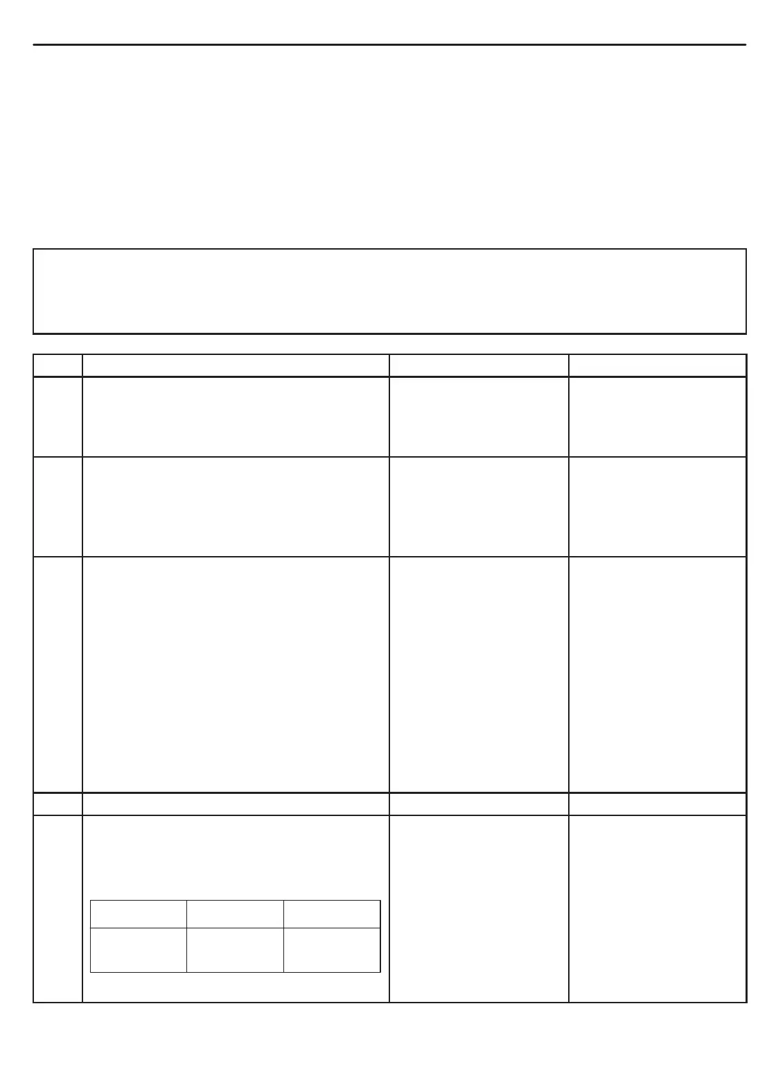
Brake pedal Released Depressed
Voltage 0 V
Battery
voltage
DIAGNOSTIC FLOW TABLE A-1 (NO TCC LOCK-UP OCCURS)
SYSTEM DESCRIPTION
PCM turns TCC solenoid OFF under any of the following conditions.
D Brake pedal switch: ON
D 4WD LOW switch: ON
D Cruise control module: TCC OFF command signal is output (if equipped).
D ECT: ECT < 30_C (86_F)
TROUBLESHOOTING
WARNING:
D When performing a road test, select a place where there is no traffic or possibility of a traffic accident
and very careful during testing to avoid occurrence of an accident.
D Road test should be carried out with 2 person, a driver and tester, on a level road.
STEP ACTION YES NO
1 Was “AUTOMATIC TRANSMISSION
DIAGNOSTIC FLOW TABLE” performed?
Go to Step 2. Go to “AUTOMATIC
TRANSMISSION
DIAGNOSTIC FLOW
TABLE”.
2 ECT check:
(1)Warm up engine to normal operating
temperature.
(2)Check ECT using scan tool.
Is ECT more than 30_C (86_F)?
Go to Step 3. Faulty ECT sensor, its
circuit or engine cooling
system.
If OK, substitute a known-
good PCM and recheck.
3 Perform running test under the following
conditions and check voltage between
C51-1-8 (G16/J20 engines) or C51-1-2 (H25
engine) terminal of PCM coupler and ground.
D Normal mode in “D” range.
D Transfer “2H” position.
D Cruise control is not operated (if equipped).
D Brake pedal released.
D Drive vehicle with TCC ON condition
referring to “TCC lock-up diagram” in
this section.
Is it battery voltage?
Faulty TCC solenoid
valve, its circuit or
transmission.
Go to Step 4.
4 Is vehicle equipped with H25 engine? Go to Step 5. Go to Step 6.
5 Brake switch signal inspection:
(1)With ignition switch ON, check voltage
between E61-31 terminal of PCM coupler
terminal and ground.
Is the result as specified?
Go to Step 6. Faulty brake pedal switch
or its circuit.
If OK, substitute a known-
good PCM and recheck.

 Loading...