YH4
GRAND
VITARA
8G-24 IMMOBILIZER CONTROL SYSTEM (IF EQUIPPED)
1
2
3
1
2
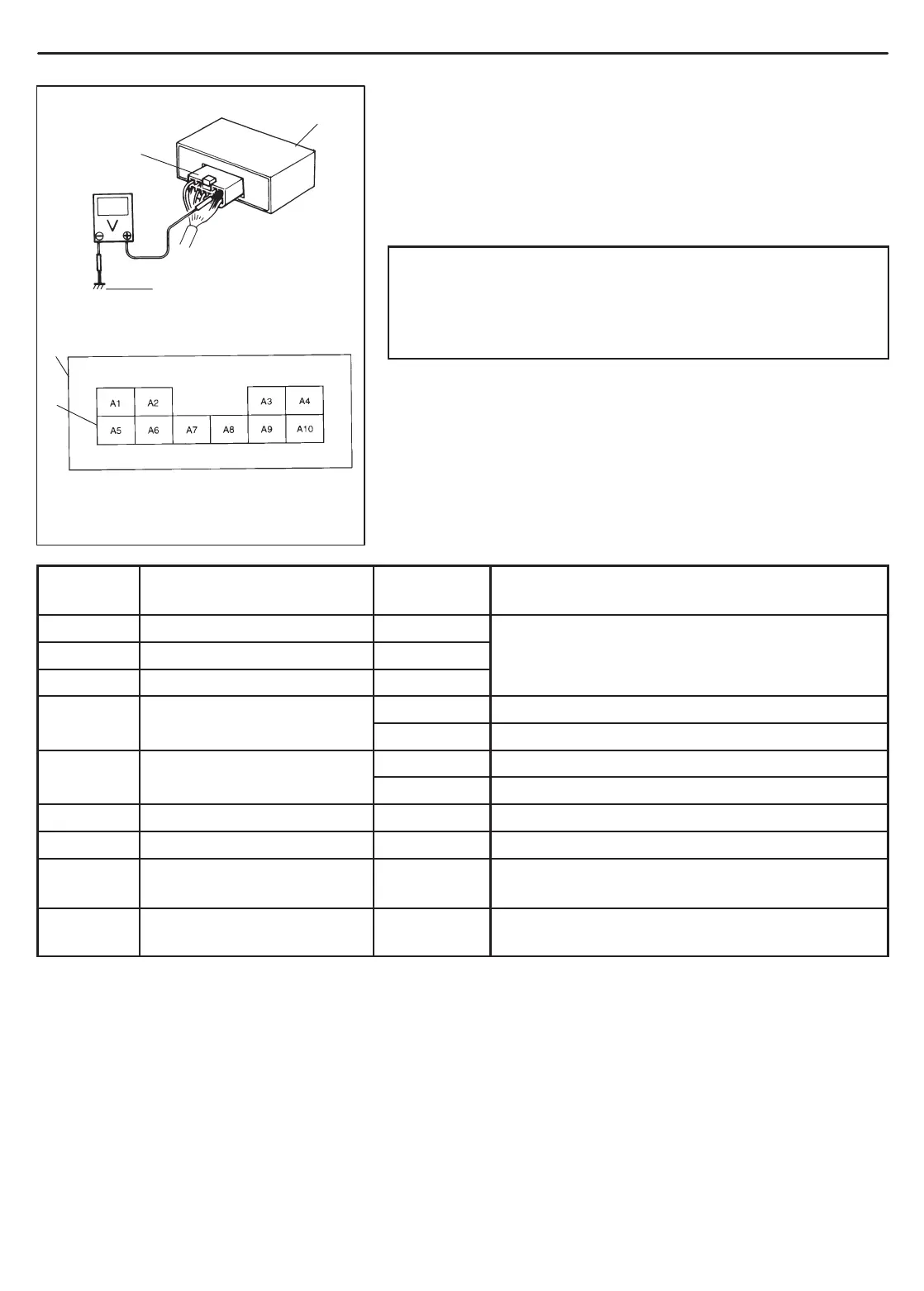
1. Immobilizer Control Module
2. Immobilizer Control Module Coupler
3. Body ground
INSPECTION OF ECM/PCM, IMMOBILIZER
CONTROL MODULE AND ITS CIRCUIT
ECM/PCM, Immobilizer Control Module and its circuit can be
checked at ECM/PCM wiring couplers and Immobilizer Control
Module wiring coupler by measuring voltage and resistance. De-
scribed here is only inspection of Immobilizer Control Module. For
inspection of ECM/PCM, refer to “SECTION 6E1 or 6E2”.
CAUTION:
Immobilizer Control Module cannot be checked by itself. It
is strictly prohibited to connect voltmeter or ohmmeter to
Immobilizer Control Module with coupler disconnected
from it.
Voltage Check
1) Remove Immobilizer Control Module from body with ignition
switch OFF, referring to p. 8G-24.
2) Connect Immobilizer Control Module coupler to Immobilizer
Control Module.
3) Check voltage at each terminal of coupler connected.
NOTE:
As each terminal voltage is affected by the battery voltage,
confirm that it is 11 V or more when ignition switch is ON.
TERMINAL CIRCUIT
NORMAL
VOLTAGE
CONDITION
A1 Coil antenna 1 0 V
A2 Coil antenna 2 0 V
Ignition switch ON
A3 Power source 10 – 14 V
10 – 14 V Ignition switch ON
0 – 0.8 V Ignition switch OFF
p
0 – 14 V Ignition switch ON
0 V Ignition switch OFF
A6 Blank – –
A7 Ground – –
A8
Data link connector
(Serial data terminal)
4 – 5 V Ignition switch ON
A9
A10
Blank – –
NOTE:
When measuring voltage at A1 and A2 terminals with ignition switch turned ON, be sure to turn ignition
switch ON before connecting positive probe of voltmeter to A1 or A2 terminal. If it is not turned ON first,
DTC13 (Diagnostic Trouble Code 13) may be indicated.

 Loading...