YH4
GRAND
VITARA
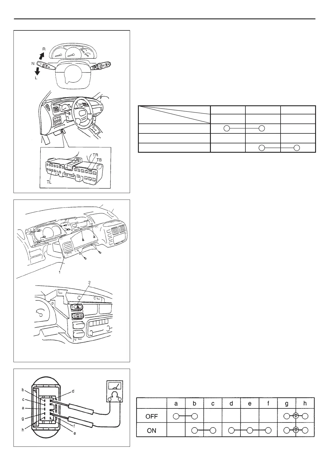
1. Meter cluster
2. Hazard switch
Terminal
Wire Color
Switch Position
LH steering vehicle shown
LIGHTING SYSTEM 8B-9
TURN SIGNAL AND HAZARD WARNING
LIGHTS
TURN SIGNAL SWITCH (IN COMBINATION SWITCH)
INSPECTION
1) Disconnect negative cable at battery.
2) Disconnect combination switch lead wire coupler.
3) Check for continuity between terminals at each switch position
shown below. If check result is not as specified, replace switch.
TL TB TR
G/R G G/Y
L
N
R
REMOVAL AND INSTALLATION
Refer to Section 3C COMBINATION SWITCH for vehicle without air
bag system and Section 3C1 CONTACT COIL AND COMBINA-
TION SWITCH ASSEMBLY for vehicle with air bag system.
HAZARD SWITCH
REMOVAL
1) Remove meter cluster.
2) Pull hazard switch out of instrument panel.
3) Disconnect coupler from hazard switch.
4) Remove hazard switch.
INSTALLATION
Reverse removal procedure.
INSPECTION
Check for continuity between terminals at each switch position
shown below. If check result is not as specified, replace siwtch.

 Loading...