YH4
GRAND
VITARA
7B1-64 AUTOMATIC TRANSMISSION (4 A/T)
1. A/T vehicle (output) speed sensor
“N” reference
line
Center line on
manual valve shaft
G16/J20
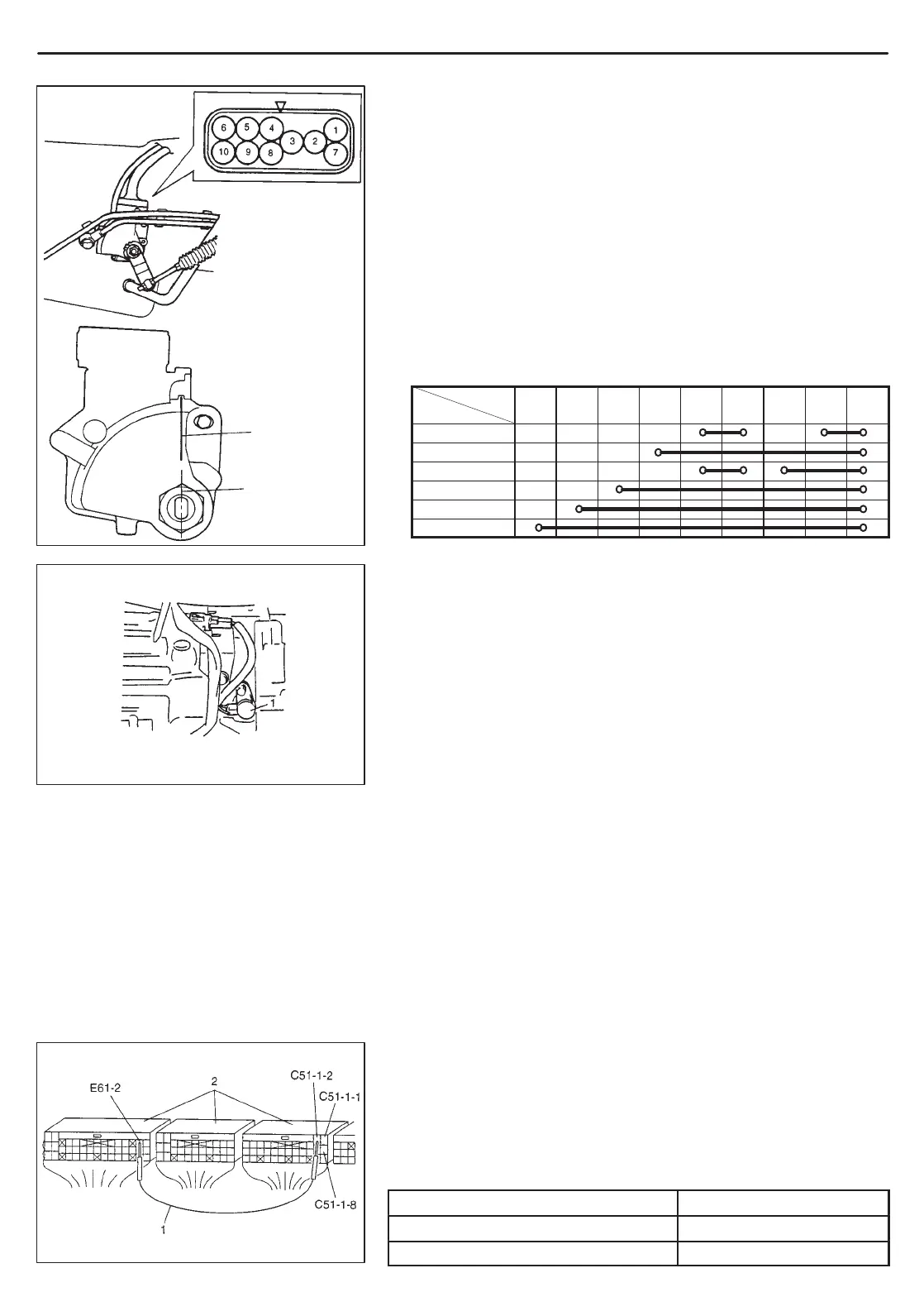
1. Service wire
2. PCM connectors disconnected
Switch
position
TRANSMISSION RANGE SWITCH (SENSOR)
INSPECTION & ADJUSTMENT
1) Shift select lever to “N” range.
2) Check that center line on manual valve shaft and “N” reference
line on switch are aligned. If not, loosen switch bolt and align
them.
3) Check that engine starts in “N” and “P” ranges but it doesn’t start
in “D”, “2”, “L” or “R” range. Also, check that back-up lamp lights
in “R” range.
4) If faulty condition cannot be corrected by adjustment, discon-
nect transmission range switch coupler and check that continu-
ity exists as shown by moving select lever.
Terminal No.
P
R
N
D
2
L
A/T OUTPUT SPEED SENSOR
INSPECTION
Check A/T output speed sensor for resistance between terminals
of sensor or PCM coupler.
A/T output speed sensor
resistance value : 387 – 473 at 20_C, 68_F
O/D CUT SWITCH
INSPECTION
Check O/D cut switch for operation referring to step 4 of Diag. Flow
Table B-2 in this section.
If malfunction is found, replace.
SOLENOID VALVES
(Shift solenoid valves & TCC solenoid valve)
INSPECTION
With couplers of PCM disconnected and using service wire as
shown at the left, check each solenoid valve for clicking sound.
G16/J20 Engines
Shift solenoid valve - A (#1) C51-1-2
Shift solenoid valve - B (#2) C51-1-1
TCC (Lock-up) solenoid valve C51-1-8

 Loading...