DS1067-062C 35 LBT20063
2.14 SYSTEM STATUS INFORMATION
Masking system status information is a mandatory requirement to be EN50131 grade 3 compliant.
Consequently, when Mode 3 (EN50131 grade 3 compliancy) is configured, system status (armed or disarmed) is not
indicated directly by the LEDs, the keypad display or the electronic key and transponder reader LEDs. The system status
may be checked by entering a valid code on the keypad or by using a valid electronic or proximity key (see the paragraphs
on how to arm and disarm the system using a key for more information).
The system status masking method may be different on each keypad and single reader but it will suffice for one of these
devices not to be masked to cancel compliance of the entire system.
This function is not available on 1067/024 control panels because these devices are EN50131 grade 2 compliant.
See chapter 1 Control devices for more information on system status visibility.
2.14.1 How to view system status
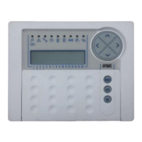
The system status is display by the LEDs provided on keypads and readers.
Each user can view the system status detail for the part assigned to them (only the zones on which the user is authorised
to operate will appear).
To view the system status:
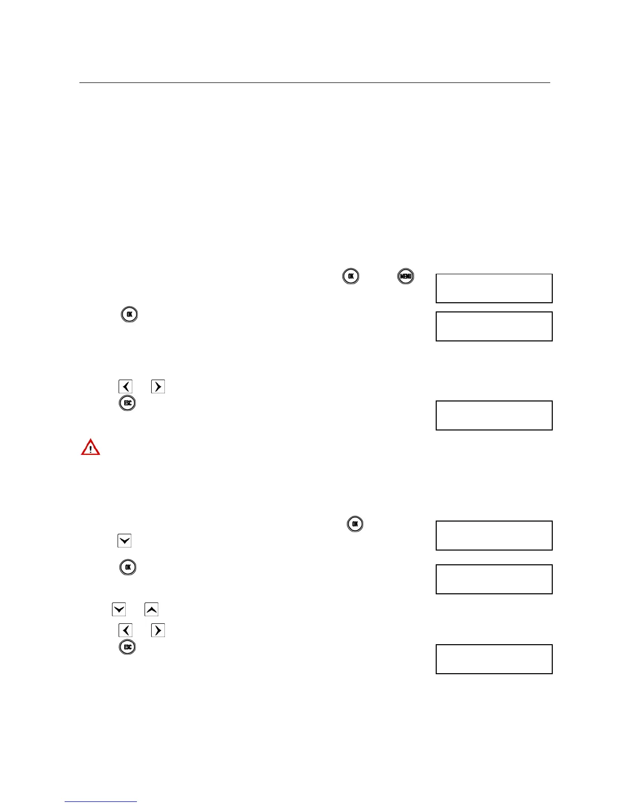
1) Enter < Master / User code / Installer / Tech. Manager > press
and then .
2) Press
. The graphic systems corresponding to digits 1 to 16 appear on the
second line of the screen. The meanings are:
□ = the zone is disarmed
0 = the zone is disarmed with one or more open inputs
■ = the zone is armed
. = the zone was not programmed
3) Press and to go from one zones to the next. The zone name will appear on the first line.
4) Press
epeatedly to exit the menu after examining the status.
IMPORTANT! Zone status can be displayed permanently instead of date and time, but this setting is not EN50131
grade 3 compliant and will declass the system.
2.14.2 How to view open inputs
The presence of one or more open inputs is indicated by the specific LED on the keypad and by the reader LED (see
chapter 1 Control devices). These LEDs also indicate the opening of isolated inputs.
To view input addresses:
1) Enter < Master / User code / Installer / Tech. Manager > press
twice and then
press
repeatedly until OPEN INPUTS appears.
2) Press
. The inputs are identified as “<Logical address>:<Name>” on the second
line. For example, an input to which the kitchen detector is connected with logical
address “3” and named “Kitchen” will be identified as “In003:Kitchen”.
3) Use
and to scroll the list of open inputs.
4) Press and to see the input customisation.
5) Press repeatedly to exit from the menu after examining the list.
UT01:MASTER
SYSTEM STATUS
ZN01:...
□□0□■...
1067/052A
12/01/2014 10:10
UT02:...
OPEN INPUTS
OPEN INPUTS
In001:...
1067/052A
12/01/2014 10:10
 Loading...