DS1067-062C 9 LBT20063
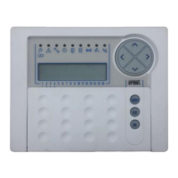
1.1.2.1 Use of LEDs with EN50131 grade 3
The keypad LED indications which are visible without needing to enter a valid code depend on the EN50131 grade (Mode
3, Mode 2 or Mode 0) set during programming.
IMPORTANT! Mode 0 (currently present) cannot be used.
Behaviour in Mode 2 is two-fold: all LED indications are visible when the alarm system is disarmed, while only the power,
timed programmer and system status indications appear when the system is armed (the other LED indications may be
viewed by entering a valid code). This use mode is EN50131 grade 2 compliant.
The alarm system is EN50131 grade 3 compliant in Mode 3. LED indications are not always visible and depend on system
status (armed or disarmed) and whether a valid access code is entered. The indications shown refer to the zones
associated to the keypad only.
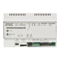
IMPORTANT! Mode 3 is not available for the 1067/024 control panel because this device is EN50131 grade 2,
and not grade 3, compliant.
Table 4 – LED indication visibility of 1067/022 keypad complying with EN50131 grade 3, shows how the LEDs behave on the
keypad in Mode 3.
Enter a valid code to see details on the indications.
All indications can be deleted using the Installer or Technical Manager codes. Only burglar, power failure and
communication failure indications can be deleted with the Master or User codes.
Alarm system status Armed Disarmed
Access code used No code
Master /
User
Installer /
Technical
Manager
No code
Master /
User
Installer /
Technical
Manager
Power LED
■ ■ ■ ■ ■ ■
Failure or warning LED
□ □ ■ ■ ■
Maintenance LED
□ □ ■ ■ ■
Timed programmer LED
■ ■ ■ ■ ■ ■
Open inputs LED
□ □ ■ ■ ■
Inhibited or isolated input LED
□ □
□ □
Alarm LED
□ □
□ □
Tamper LED
□ □
□ □
System status LED
□ □
□ □
■ = The LED indication is always visible even without entering an access code.
□ = The LED indication is only visible after having entered a valid access code.
Table 4 – LED indication visibility of 1067/022 keypad complying with EN50131 grade 3
1.1.3 Zone indications
The zones status is shown on the display in graphic mode.
The graphic symbols corresponding to digits 1 to 16 appear on the second line of the
screen.
The meanings are:
Symbol During normal use During programming
□
Zone disarmed Zone not associated to the function
■
Zone armed Zone associated to the function
0
Zone disarmed with one or more open inputs -
.
Zone does not exist Zone does not exist
Example for 1067/052A
Zone 4 is armed, Zones 1, 2, 5 and 6 are disarmed, Zone 3 is disarmed with one or more
open inputs, Zones from 7 to 16 do not exist.
SYSTEM STATUS
□□□□□□..........
SYSTEM STATUS
□□0■□□..........
1 2 3 4 5 6 7 8 9 10 1112131415 16
1 2 3 4 5 6 7 8 9 10 1112131415 16
 Loading...