FRONT BRAKE
4-41
d. Measure the brake disc runout.
e. If out of specification, repeat the adjustment
steps until the brake disc runout is within
specification.
f. If the brake disc runout cannot be brought
within specification, replace the brake disc.
▲▲▲▲▲▲▲▲▲▲▲▲▲▲▲▲▲▲▲▲▲▲▲▲▲▲▲▲▲▲▲▲
6. Install:
• Front wheel
Refer to “FRONT WHEEL” on page 4-19.
EAS30170
REPLACING THE FRONT BRAKE PADS
The following procedure applies to both brake
calipers.
When replacing the brake pads, it is not neces-
sary to disconnect the brake hose or disassem-
ble the brake caliper.
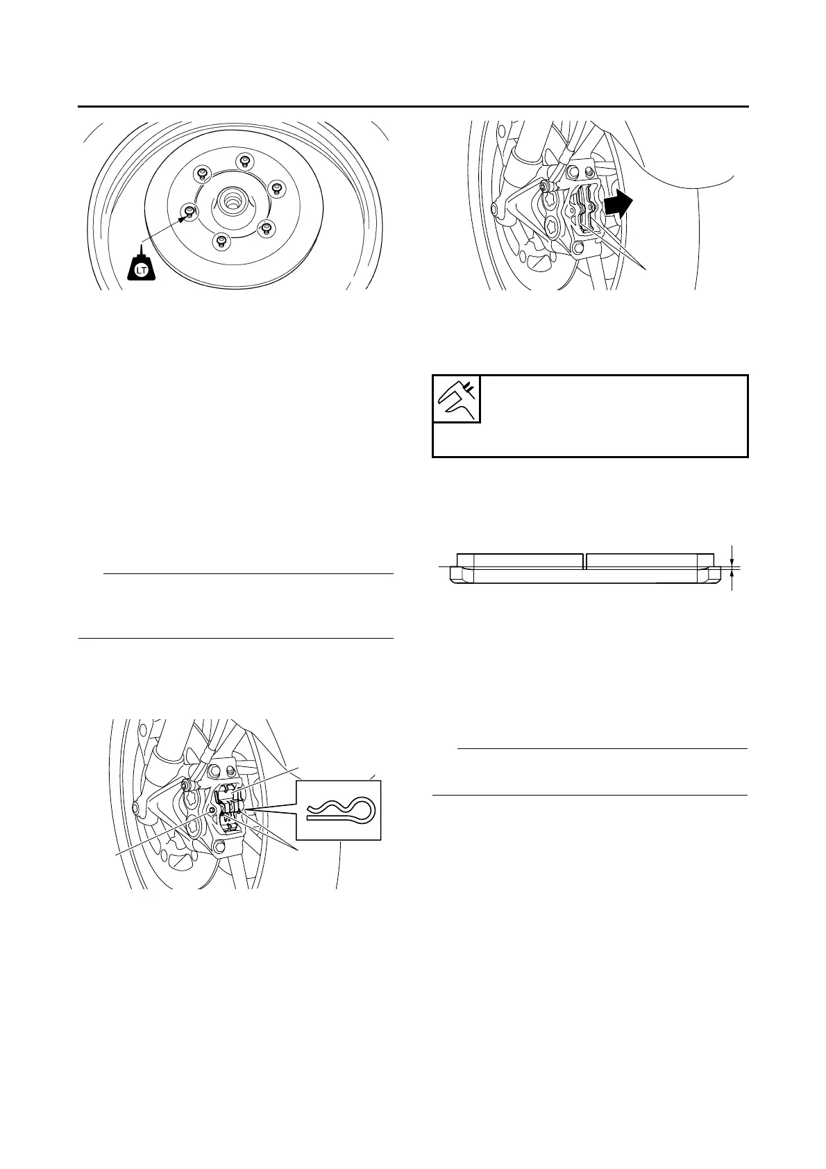
1. Remove:
• Brake pad clips “1”
• Brake pad pin “2”
• Brake pad spring “3”
2. Remove:
• Brake pads “1”
3. Measure:
• Brake pad wear limit “a”
Out of specification Replace the brake
pads as a set.
4. Remove:
• Brake caliper bolts
5. Install:
• Brake pads
• Brake pad spring
Always install new brake pads and new brake
pad spring as a set.
▼▼▼▼▼▼▼▼▼▼▼▼▼▼▼▼▼▼▼▼▼▼▼▼▼▼▼▼▼▼▼▼
a. Connect a clear plastic hose “1” tightly to the
bleed screw “2”. Put the other end of the hose
into an open container.
b. Loosen the bleed screw and push the brake
caliper pistons into the brake caliper with your
finger.
Brake pad lining thickness
4.5 mm (0.18 in)
Limit
0.5 mm (0.02 in)

 Loading...