ABS (ANTI-LOCK BRAKE SYSTEM)
4-63
EAS30197
REMOVING THE HYDRAULIC UNIT
ASSEMBLY
ECA21091
Unless necessary, avoid removing and in-
stalling the brake hoses of the hydraulic unit
assembly.
EWA13930
Refill with the same type of brake fluid that is
already in the system. Mixing fluids may re-
sult in a harmful chemical reaction, leading
to poor braking performance.
ECA18241
• Handle the ABS components with care
since they have been accurately adjusted.
Keep them away from dirt and do not sub-
ject them to shocks.
• Do not turn the main switch to “ON” when
removing the hydraulic unit assembly.
• Do not clean with compressed air.
• Do not reuse the brake fluid.
• Brake fluid may damage painted surfaces
and plastic parts. Therefore, always clean
up any spilt brake fluid immediately.
• Do not allow any brake fluid to contact the
couplers. Brake fluid may damage the cou-
plers and cause bad contacts.
• If the union bolts for the hydraulic unit as-
sembly have been removed, be sure to
tighten them to the specified torque and
bleed the brake system.
1. Disconnect:
• ABS ECU coupler “1”
Pull the lock lever “a” of the ABS ECU coupler in
the direction of the arrow shown, and then dis-
connect the coupler.
2. Remove:
• Brake hoses
Do not operate the brake lever and brake pedal
while removing the brake hoses.
ECA18251
When removing the brake hoses, cover the
area around the hydraulic unit assembly to
catch any spilt brake fluid. Do not allow the
brake fluid to contact other parts.
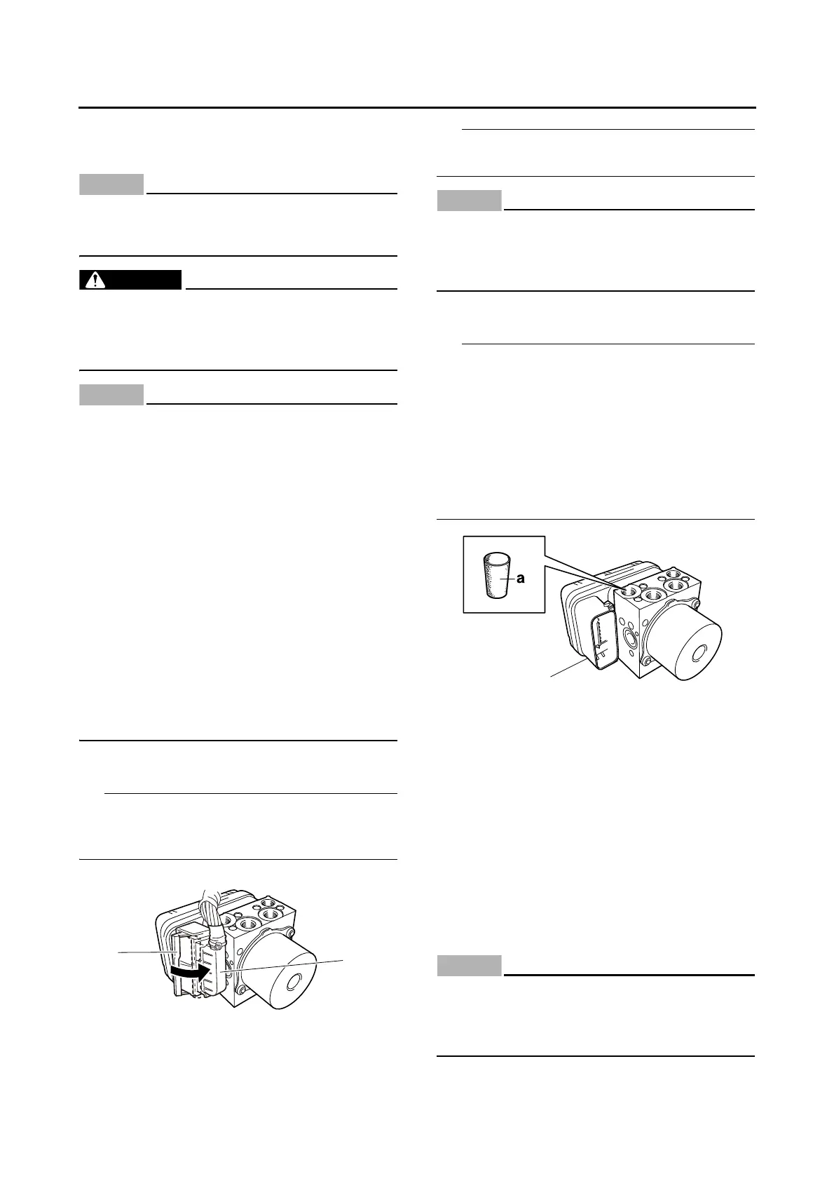
3. Remove:
• Hydraulic unit assembly “1”
• To avoid brake fluid leakage and to prevent for-
eign materials from entering the hydraulic unit
assembly, insert a rubber plug “a” or a bolt
(M10 1.0) into each brake hose union bolt
hole.
• When using a bolt, do not tighten the bolt until
the bolt head touches the hydraulic unit. Other-
wise, the brake hose union bolt seating surface
could be deformed.
EAS30198
CHECKING THE HYDRAULIC UNIT
ASSEMBLY
1. Check:
• Hydraulic unit assembly
Cracks/damage Replace the hydraulic unit
assembly and the brake pipes that are con-
nected to the assembly as a set.
EAS30200
INSTALLING THE HYDRAULIC UNIT
ASSEMBLY
1. Install:
• Hydraulic unit assembly
ECA21371
Do not remove the rubber plugs or bolts
(M10 1.0) installed in the brake hose union
bolt holes before installing the hydraulic unit
assembly.

 Loading...