CAMSHAFTS
5-11
EAS30256
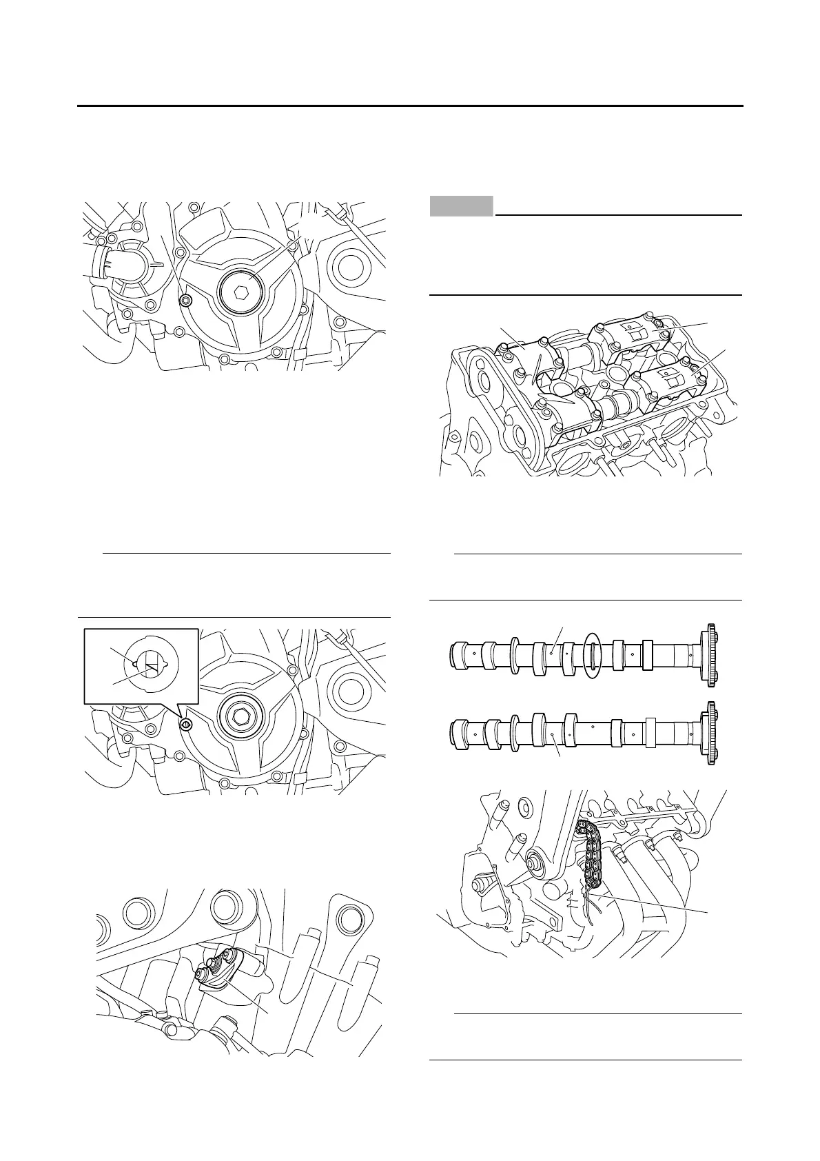
REMOVING THE CAMSHAFTS
1. Remove:
• Timing mark accessing bolt “1”
• Crankshaft end cover “2”
2. Align:
• Mark “a” on the generator rotor
(with the generator rotor cover mark “b”)
▼▼▼▼▼▼▼▼▼▼▼▼▼▼▼▼▼▼▼▼▼▼▼▼▼▼▼▼▼▼▼▼
a. Turn the crankshaft counterclockwise.
b. When piston #1 is at BTDC125 on the com-
pression stroke, align the BTDC125 mark “a”
on the generator rotor with the generator rotor
cover mark “b”.
BTDC125 on the compression stroke can be
found when the camshaft lobes are turned away
from each other.
▲▲▲▲▲▲▲▲▲▲▲▲▲▲▲▲▲▲▲▲▲▲▲▲▲▲▲▲▲▲▲▲
3. Remove:
• Timing chain tensioner “1”
• Timing chain tensioner gasket
4. Remove:
• Camshaft cap “1”
• Intake camshaft cap “2”
• Exhaust camshaft cap “3”
ECA13720
To prevent damage to the cylinder head,
camshafts or camshaft caps, loosen the
camshaft cap bolts in stages and in a criss-
cross pattern, working from the outside in.
5. Remove:
• Intake camshaft “1”
• Exhaust camshaft “2”
To prevent the timing chain from falling into the
crankcase, fasten it with a wire “3”.
6. Remove:
• Camshaft sprocket “1”
Use the camshaft wrench “2” and loosen the
camshaft sprocket bolt.

 Loading...