VALVES AND VALVE SPRINGS
5-25
▲▲▲▲▲▲▲▲▲▲▲▲▲▲▲▲▲▲▲▲▲▲▲▲▲▲▲▲▲▲▲▲
3. Eliminate:
• Carbon deposits
(from the valve face and valve seat)
4. Check:
• Valve face
Pitting/wear Grind the valve face.
• Valve stem end
Mushroom shape or diameter larger than the
body of the valve stem Replace the valve.
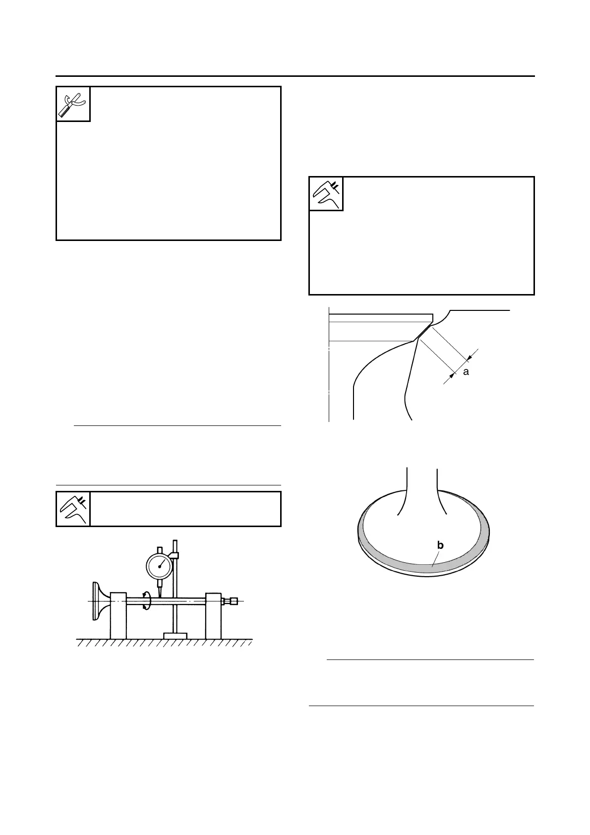
5. Measure:
• Valve stem runout
Out of specification Replace the valve.
• When installing a new valve, always replace
the valve guide.
• If the valve is removed or replaced, always re-
place the valve stem seal.
EAS30285
CHECKING THE VALVE SEATS
The following procedure applies to all of the
valves and valve seats.
1. Eliminate:
• Carbon deposits
(from the valve face and valve seat)
2. Check:
• Valve seat
Pitting/wear Replace the cylinder head.
3. Measure:
• Valve seat contact width “a”
Out of specification Replace the cylinder
head.
▼▼▼▼▼▼▼▼▼▼▼▼▼▼▼▼▼▼▼▼▼▼▼▼▼▼▼▼▼▼▼▼
a. Apply blue layout fluid “b” onto the valve face.
b. Install the valve into the cylinder head.
c. Press the valve through the valve guide and
onto the valve seat to make a clear impres-
sion.
d. Measure the valve seat contact width.
Where the valve seat and valve face contacted
one another, the blue layout fluid will have been
removed.
▲▲▲▲▲▲▲▲▲▲▲▲▲▲▲▲▲▲▲▲▲▲▲▲▲▲▲▲▲▲▲▲
4. Lap:
• Valve face
• Valve seat
Valve guide remover (ø4.5)
90890-04116
Valve guide remover (4.5 mm)
YM-04116
Valve guide installer (ø4.5)
90890-04117
Valve guide installer (4.5 mm)
YM-04117
Valve guide reamer (ø4.5)
90890-04118
Valve guide reamer (4.5 mm)
YM-04118
Valve stem runout
0.010 mm (0.0004 in)
Valve seat contact width (intake)
0.90–1.10 mm (0.0354–0.0433 in)
Limit
1.60 mm (0.06 in)
Valve seat contact width (ex-
haust)
1.10–1.30 mm (0.0433–0.0512 in)
Limit
1.80 mm (0.07 in)

 Loading...