$GYDQW
&RQWUROOHU8VHU¶V*XLGH
6HFWLRQ *HQHUDO6\VWHP8WL OLWLHV
3BSE 002 415R701 Rev A 3-3
$GGLWLRQDO6XSHUYLVRU\,QSXWV
No extra hardware or software is needed.
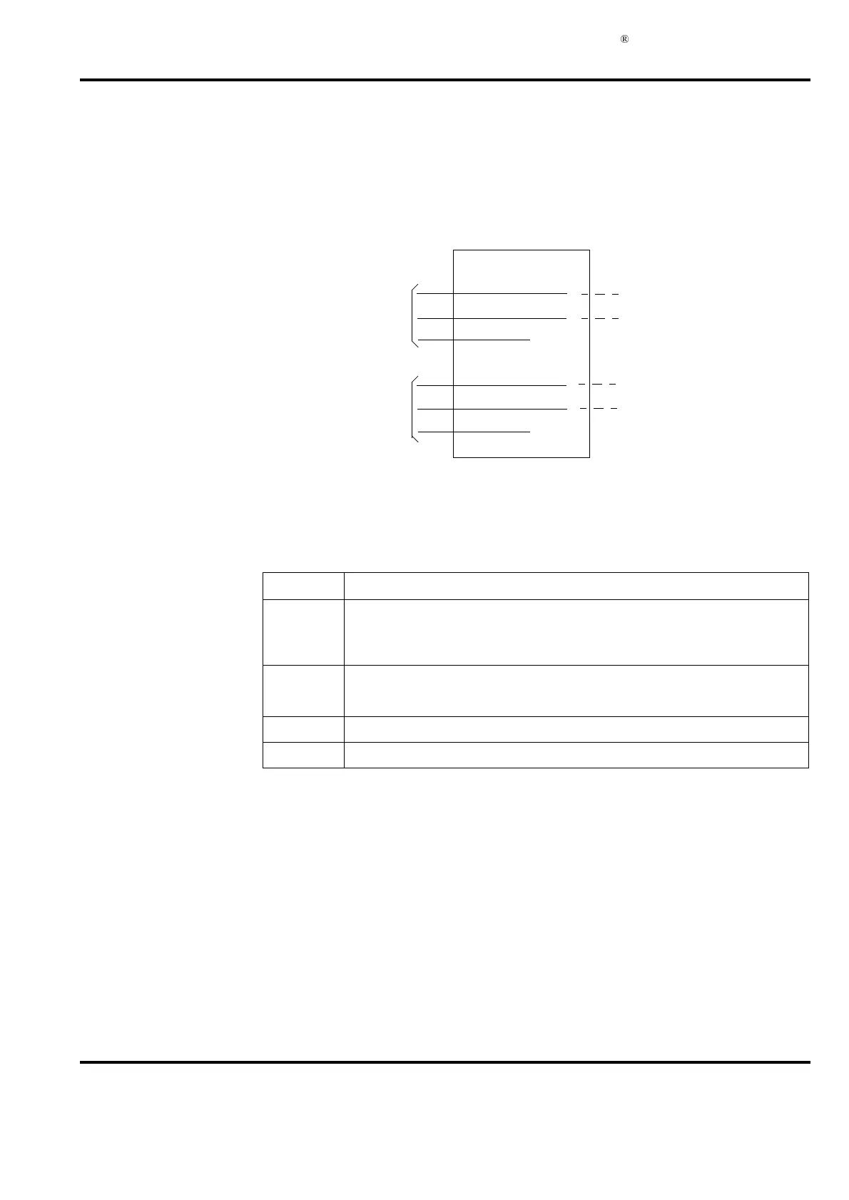
The Supervision Unit TC520 is used according to Figure 3-3.
Electrical data: see the module description in Appendix A, Hardware Modules.
Application: see Section 2.2.8, Controller, heading Electric Installation.
Note that input A1 may be used HLWKHU for supervision of 24V A in I/O subracks 25 user
defined function F1.
For supervision of 24V A in I/O subracks, set terminal IO24VA to “YES”.
For supervision of user defined function F1, set terminal F1 to “YES”.
Input A2 may be used HLWKHU for supervision of 24V B in I/O stations 25 user defined function
F2.
)LJXU H &RQQHFWLRQRI$GGLWLRQDO6XS HUYLVRU\,QSXWV
)LJXU H 3RZHU6XSSO\7HUPLQDO6HWWLQJV
7HUPLQDO 6HWWLQJ
F1 “NO”. (Because normally the signal “I/O 24V A error” is connected to digital input
A1 of TC520
(1)
).
(1) See sections “Power Supply modules” and “TC520” in the Data Base Elements Advant
Controller 400 Series - Reference Manual.
(“YES” if there is a user defined signal connected to digital input A1 of TC520
(1)
).
F2 “NO” if the signal “I/O 24V B error” is connected to digital input A2 of TC520
(1)
.
“YES” if there is a user defined signal connected to digital input A2 of TC520
(1)
.
F3 “YES” if there is a user defined signal connected to digital input B1 of TC520
(1)
.
F4 “YES” if there is a user defined signal connected to digital input B2 of TC520
(1)
.
7&
1
2
3
STATUS A1
STATUS A2
COMMON A
4
5
6
STATUS B1
STATUS B2
COMMON B
Free disposition
within cabinets
Reserved for
diagnostics at
redundancy
power supply
System status display
in operator station
(I/O) 24 V supply A or F1
(I/O) 24 V supply B or F2
F3
F4
Configuration: DB element AC450
 Loading...


