Home
Fujitsu
Server
PRIMERGY TX140 S1
Fujitsu PRIMERGY TX140 S1 Upgrade And Maintenance Manual
4
of 1
of 1 rating
588 pages
Give review
Manual
Specs
To Next Page
To Next Page
To Previous Page
To Previous Page
Loading...
432
Upgrade and Mai
ntenance Manual
TX140
S1
System board and compo
nent
s
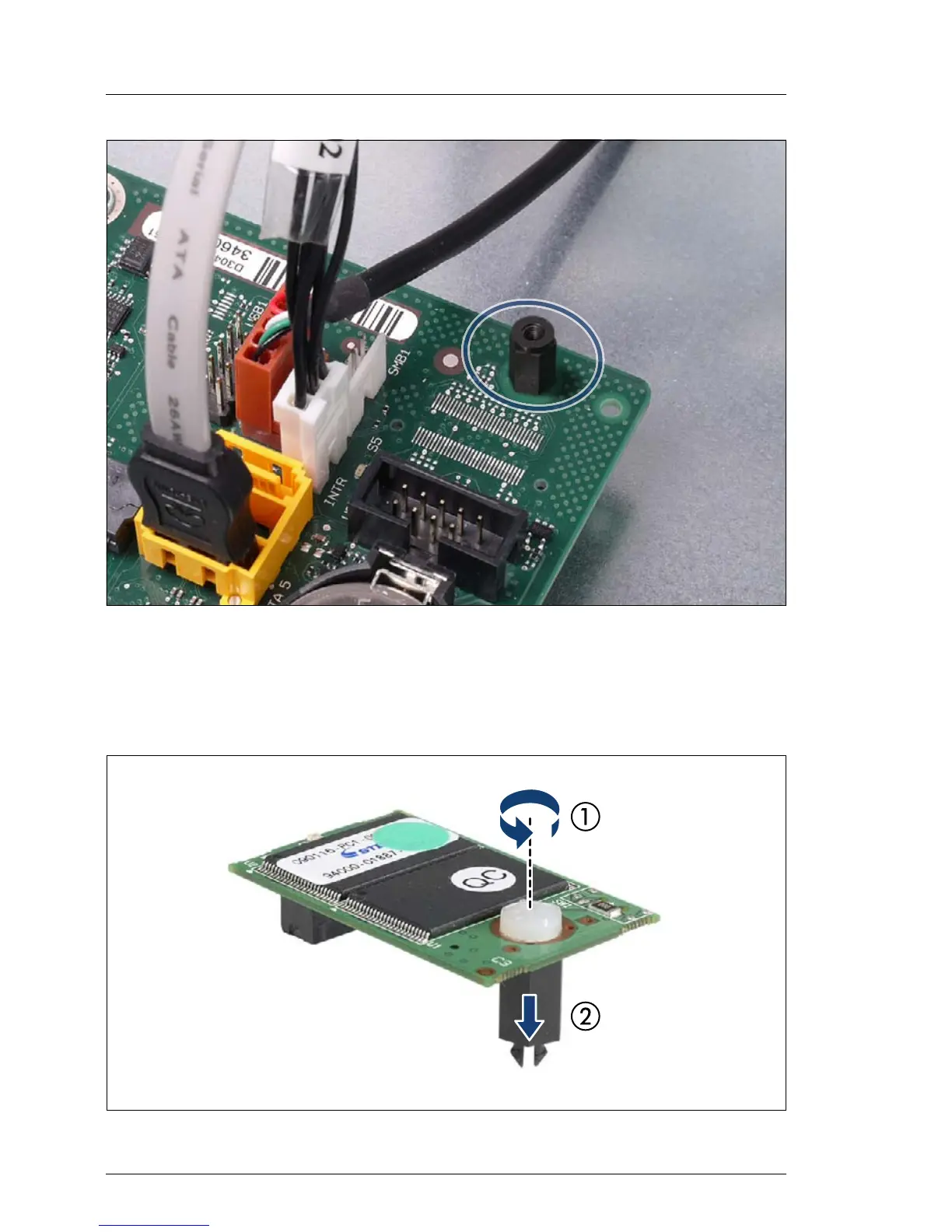
Figure 275: Removing the UFM board (B)
Ê
The UFM spacer remains on the system board.
14.2.3.4
Re-installing the UFM
Figure 276: Prep
aring the new UFM board
431
433
Table of Contents
Table of Contents
7
Default Chapter
2
Copyright and Trademarks
2
Version History
23
1 Introduction
25
Where to Find Which Information
26
Notational Conventions
28
2 Before You Start
29
Classification of Procedures
31
Customer Replaceable Units (CRU)
31
Upgrade and Repair Units (URU)
32
Field Replaceable Units (FRU)
33
Average Task Duration
34
Tools You Need at Hand
35
Documents You Need at Hand
37
3 Important Information
41
Safety Instructions
41
Energy Star
49
CE Conformity
49
FCC Class a Compliance Statement
50
Environmental Protection
51
4 Basic Hardware Procedures
53
Using Diagnostics Information
53
Locating the Defective Server
54
Determining the Error Class
55
Global Error Indicator
55
Customer Self Service (CSS) Indicator
56
Locating the Defective Component
57
Local Diagnostic Indicators on the Front
57
Local Diagnostic Indicators on the System Board
59
Opening the Rack Door
61
Shutting down the Server
61
Extending / Removing the Server from the Rack
64
Preliminary Steps
64
Extending the Server out of the Rack
65
Removing the Server from the Rack
66
Opening the Server
67
Rack Model
67
Removing the Top Cover
67
Removing the Rack Front Cover
69
Tower Model
71
Removing the Side Cover
71
Removing the Front Cover
74
Removing the HDD Bay Cover
76
Closing the Server
77
Rack Model
77
Mounting the Rack Front Cover
77
Mounting the Top Cover
80
Tower Model
82
Mounting the Front Cover
82
Installing the HDD Bay Cover
84
Mounting the Side Cover
85
Mounting the Server in the Rack
87
Seating the Server on the Rack Rails
87
Sliding the Server into the Rack
89
Connecting the Server to the Mains
90
Switching on the Server
91
4.10 Concluding Software Tasks
92
Default Chapter
92
Closing the Rack Door
92
Concluding Software Tasks
92
5 Basic Software Procedures
93
Starting the Maintenance Task
93
Disabling Bitlocker Functionality
93
Disabling SVOM Boot Watchdog Functionality
94
Viewing Boot Watchdog Settings
94
Configuring Boot Watchdog Settings
95
Removing Backup and Optical Disk Media
96
Verifying and Configuring the Backup Software Solution
96
Note on Server Maintenance in a Multipath I/O Environment
97
Switching on the ID Indicator
99
Completing the Maintenance Task
100
Updating or Recovering the System Board BIOS and Irmc
100
Updating or Recovering the System Board BIOS
100
Updating or Recovering the Irmc
102
Verifying System Information Backup / Restore
104
Updating RAID Controller Firmware
105
Enabling Option ROM Scan
106
Verifying and Configuring the Backup Software Solution
107
Resetting the Boot Retry Counter
108
Viewing the Boot Retry Counter
108
Enabling SVOM Boot Watchdog Functionality
110
Enabling Replaced Components in the System BIOS
111
Verifying the Memory Mode
111
Verifying the System Time Settings
112
Viewing and Clearing the System Event Log (SEL)
113
Viewing the SEL
113
Clearing the SEL
114
Updating the NIC Configuration File in a Linux Environment
114
Enabling Bitlocker Functionality
116
Performing a RAID Array Rebuild
117
Looking up Changed MAC / WWN Addresses
117
Looking up MAC Addresses
117
Looking up WWN Addresses
118
Using the Chassis ID Prom Tool
119
Configuring LAN Teaming
119
After Replacing / Upgrading LAN Controllers
120
After Replacing the System Board
120
Switching off the ID Indicator
120
Specifying the Chassis Model
121
6 Power Supply
123
Standard Power Supply
124
Replacing the Standard Power Supply Unit
124
Required Tools
124
Preliminary Steps
124
Disconnecting Power Cables
126
Removing the Standard Power Supply Unit
128
Installing the Standard Power Supply Unit
130
Reconnecting Power Cables
132
Concluding Steps
134
Converting a Standard Power Supply to a Redundant Power Supply
135
Required Tools
135
Preliminary Steps
136
Disconnecting Power Cables
136
Removing the Standard Power Supply Unit
137
Installing the PSU Cage
137
Connecting Power Cables
140
Installing the Power Supply Module
142
Installing the PSU Dummy Cover
143
Concluding Steps
144
Redundant Power Supply
145
Installing the Second Power Supply Module
145
Required Tools
145
Preliminary Steps
145
Removing the Dummy Cover
146
Installing the Power Supply Module
147
Concluding Steps
148
Replacing a Power Supply Module
149
Required Tools
149
Preliminary Steps
150
Removing the Power Supply Module
150
Installing the New Power Supply Module
151
Concluding Steps
151
Replacing the Power Distribution Board
152
Required Tools
152
Preliminary Steps
152
Removing the PSU Modules
154
Disconnecting the Power Cables
155
Replacing the Defective Power Distribution Board
156
Connecting the Power Cables
157
Installing the PSU Module / Dummy Cover
157
Concluding Steps
158
7 Hard Disk Drives / Solid State Drives
159
7.1 Basic Procedure
160
Basic Procedure
160
Inch Hard Disk Drives / Solid State Drives
161
Mounting Order for 2.5-Inch Hdds / Ssds
161
Installing 2.5-Inch HDD / SSD Modules
163
Required Tools
163
Preliminary Steps
164
Removing a 2.5-Inch HDD / SSD Dummy Module
164
Installing a 2.5-Inch HDD / SSD Module
165
Concluding Steps
167
Preliminary Steps
167
Removing 2.5-Inch HDD / SSD Modules
167
Required Tools
167
Removing a 2.5-Inch HDD / SSD Module
168
Concluding Steps
170
Installing a 2.5-Inch HDD / SSD Dummy Module
170
Preliminary Steps
171
Replacing a 2.5-Inch HDD / SSD Module
171
Required Tools
171
Concluding Steps
172
Installing a 2.5-Inch HDD / SSD Module
172
Removing a 2.5-Inch HDD / SSD Module
172
Inch Hard Disk Drives
173
Mounting Order for 3.5-Inch Hdds
173
Installing 3.5-Inch HDD Modules
175
Preliminary Steps
175
Required Tools
175
Removing a 3.5-Inch HDD Dummy Module
176
Installing a 3.5-Inch HDD Module
177
Concluding Steps
179
Preliminary Steps
179
Removing 3.5-Inch HDD Modules
179
Required Tools
179
Removing a 3.5-Inch HDD Module
180
Concluding Steps
182
Installing a 3.5-Inch HDD Dummy Module
182
Preliminary Steps
183
Replacing a 3.5-Inch HDD Module
183
Required Tools
183
Concluding Steps
184
Installing a 3.5-Inch HDD Module
184
Removing a 3.5-Inch HDD Module
184
Preliminary Steps
185
Replacing SAS / SATA HDD / SSD Backplanes
185
Replacing the 2.5-Inch HDD SAS / SATA Backplane
185
Required Tools
185
Removing the 2.5-Inch HDD SAS / SATA Backplane
187
Installing the 2.5-Inch HDD SAS / SATA Backplane
190
Concluding Steps
193
Preliminary Steps
194
Replacing the 3.5-Inch HDD SAS / SATA Backplane
194
Required Tools
194
Removing the 3.5-Inch HDD SAS / SATA Backplane
195
Installing the 3.5-Inch HDD SAS / SATA Backplane
199
Concluding Steps
203
8 System Fan and Air Duct
205
Replacing the Fan Module
207
Required Tools
207
Preliminary Steps
207
Removing the Fan Module
208
Installing the Fan Module
209
Concluding Steps
212
Replacing the Fan in the Fan Module
212
Required Tools
212
(Rack Server) or "Mounting the Side Cover
212
Perform the Following Procedures to Complete the Task
212
Ê Close the Side / Top Cover as Described in Section "Mounting the Top Cover
212
Ê When Working on a Rack-Mounted Server, Secure It in the Rack as Described in Section "Sliding the Server into the Rack" on Page
212
Preliminary Steps
213
Removing the Fan
214
Installing the Fan
218
Concluding Steps
221
Mounting the Server in the Rack" on Page
221
Ê if Applicable, Close the Rack Door as Described in Section "Closing the Rack Door" on Page
222
Ê Reconnect the AC Power Cord to the Power Supply Unit and Secure It with a Cable Tie as Described in Section "Connecting the Server to the Mains" on Page
222
9 Expansion Cards and Backup Units
223
Basic Procedure
224
Expansion Cards
226
Installing Expansion Cards
226
Required Tools
226
Preliminary Steps
227
Removing PCI Slot Bracket
228
Installing an Expansion Card
230
Connecting Cables to the Expansion Card
231
Connecting a Battery Backup Unit to the Expansion Card
231
Concluding Steps
232
Removing Expansion Cards
233
Required Tools
233
Preliminary Steps
233
Removing an Expansion Card
234
Installing a PCI Slot Bracket
236
Concluding Steps
237
Replacing Expansion Cards
238
Required Tools
238
Preliminary Steps/Removing an Expansion Card
239
Default Chapter
239
Preliminary Steps
239
Removing an Expansion Card
239
Concluding Steps
240
Connecting a Battery Backup Unit to the Expansion Card
240
Connecting Cables to the Expansion Card
240
Installing an Expansion Card
240
Preliminary Steps
242
Ê Disable Bitlocker Functionality as Described in Section
242
Replacing the TFM
242
Required Tools
242
Installing the New TFM
243
Removing the Defective TFM
243
Concluding Steps
244
Backup Units (BBU/FBU)
245
Installing a BBU
245
Preliminary Steps
245
Door" on Page
245
Server" on Page
245
SVOM Boot Watchdog Functionality" on Page
245
Required Tools
245
Preparing the BBU
246
If Further Required, Remove the Server from the Rack as Described in Section "Removing the Server from the Rack" on Page
246
On Page
246
Ê Open the Side / Top Cover as Described in Section
246
Installing the BBU Holder into the Chassis
249
Concluding Steps
252
On Page
252
Installing a FBU
254
Preliminary Steps
254
Required Tools
254
Installing TFM to the RAID Controller (if Applicable)
255
Preparing the FBU
256
Installing the FBU Holder into the Chassis
258
Concluding Steps
259
Connecting the FBU Adapter Cable to the TFM
259
Preliminary Steps
260
Removing a BBU
260
Required Tools
260
Removing the BBU Holder from the Chassis
261
Concluding Steps
263
Preliminary Steps
264
Removing a FBU
264
Required Tools
264
Concluding Steps
265
Disconnecting the FBU Adapter Cable from the TFM
265
Removing the FBU Holder from the Chassis
265
Preliminary Steps
266
Replacing a BBU
266
Required Tools
266
Removing a BBU from the Chassis
267
Removing the BBU from the BBU Holder
267
Concluding Steps
270
Installing a New BBU
270
Replacing a FBU
271
Preliminary Steps
272
Removing the FBU from the Chassis
272
Required Tools
272
Removing the FBU from the FBU Holder
273
Installing a Replacement FBU
274
Concluding Steps
275
Additional Tasks
276
Mounting Expansion Card Slot Brackets
276
Required Tools
276
General Instructions
277
Network Adapter D2735
278
Network Adapter D2745
280
Network Adapter D2755
282
Handling SFP+ Transceiver Modules
284
Installing SFP+ Transceiver Modules
284
Removing an SFP+ Transceiver Module
289
Replacing SFP+ Transceiver Modules
291
10 Main Memory
293
Basic Procedure
294
Memory Sequence
294
Operation Modes
295
Installing Memory Modules
296
Required Tools
296
Preliminary Steps
296
Installing a Memory Module
297
Concluding Steps
299
Removing Memory Modules
300
Required Tools
300
Preliminary Steps
300
Removing a Memory Module
301
Concluding Steps
302
Replacing Memory Modules
303
Required Tools
303
Preliminary Steps
303
Removing a Memory Module
304
Installing a Memory Module
304
Concluding Steps
305
11 Processors
307
Basic Procedure
308
Upgrading or Replacing the Processor
308
Required Tools
308
Preliminary Steps
308
Removing the Processor Heat Sink
310
Removing the Processor
312
Installing the Processor
315
Applying Thermal Paste
319
Installing the Processor Heat Sink
321
Concluding Steps
323
Replacing the Processor Heat Sink
324
Required Tools
324
Preliminary Steps
325
Removing the Processor Heat Sink
325
Applying Thermal Paste
325
Installing the Processor Heat Sink
325
Concluding Steps
326
12 Accessible Drives
327
Basic Procedure
328
Installing Accessible Drives
330
Required Tools
330
Preliminary Steps
330
Removing the Accessible Drive Dummy Module
331
Installing an Optical Disk Drive (ODD)
332
Preparing the Optical Disk Drive
332
Installing the Optical Disk Drive
334
Installing a Slimline Optical Disk Drive (ODD)
337
Mounting the Slimline Drive in the Slide-In Unit
337
Preparing the Slide-In Unit
338
Installing the Slimline Drive
341
Installing a Backup Drive
344
Preparing the Backup Drive
344
Installing the Backup Drive
347
Concluding Steps
350
Removing Accessible Drives
351
Required Tools
351
Preliminary Steps
351
Removing an Optical Disk Drive (ODD)
352
Removing a Slimline Optical Disk Drive (ODD)
354
Removing a Backup Drive
356
Installing Accessible Drive Dummy Modules
358
Preparing the Accessible Drive Dummy Module
358
Installing the Accessible Drive Dummy Module
360
Concluding Steps
361
Replacing Accessible Drives
362
Required Tools
362
Preliminary Steps
362
Replacing an Optical Disk Drive (ODD)
363
Replacing a Slimline Optical Disk Drive (ODD)
365
Replacing a Backup Drive
367
Concluding Steps
369
13 Front Panel and External Connectors
371
Replacing the Front Panel Module
372
Required Tools
372
Preliminary Steps
373
Removing the Front Panel Module
374
Installing the Front Panel Module
378
Concluding Steps
382
Front LAN Connector
383
Installing the Front LAN Connector
383
Required Tools
383
Preliminary Steps
383
Removing the Front Panel Module
384
Preparing the Front Panel Module
386
Installing the Front LAN Connector
389
Re-Assembling the Front Panel Module
390
Re-Installing the Front Panel Module
392
Concluding Steps
397
Using the Front Management LAN Connector
398
Removing the Front LAN Connector
399
Required Tools
399
Preliminary Steps
399
Removing the Front LAN Board
400
Removing the Front LAN Connector
403
Re-Installing the Front Panel Module
406
Concluding Steps
407
Replacing the Front LAN Connector and Board
408
Required Tools
408
Preliminary Steps
408
Removing the Front Panel Module
409
Removing the Front LAN Connector
409
Installing the New Front LAN Connector
409
Re-Assembling the Front Panel Module
409
Re-Installing the Front Panel Module
410
Concluding Steps
412
14 System Board and Components
415
Replacing the CMOS Battery
416
Required Tools
416
Preliminary Steps
417
Removing the Battery
418
Installing the CMOS Battery
420
Concluding Steps
421
USB Flash Module (UFM)
422
Installing the UFM Board
422
Required Tools
422
Preliminary Steps
422
Installing the UFM Board
423
Concluding Steps
425
Software Configuration
426
Removing the UFM Board
426
Required Tools
426
Preliminary Steps
427
Removing the UFM Board
428
Concluding Steps
429
Replacing the UFM Board
430
Required Tools
430
Preliminary Steps
430
Removing the UFM
431
Re-Installing the UFM
432
Concluding Steps
436
Software Configuration
436
Trusted Platform Module (TPM)
437
Installing the TPM Board
437
Required Tools
437
Preliminary Steps
437
Installing the TPM Board
438
Concluding Steps
442
Removing the TPM Board
443
Required Tools
443
Preliminary Steps
444
Removing the TPM Board
446
Concluding Steps
447
Replacing the TPM Board
448
Required Tools
448
Preliminary Steps
449
Removing the TPM
449
Re-Installing the TPM
450
Concluding Steps
450
Replacing the System Board
451
Required Tools
452
Preliminary Steps
454
Removing the System Board
455
Installing the System Board
460
Mounting the System Board
460
Swapping the Processor
464
Concluding Steps
469
15 Converting a Tower Server to a Rack Server
473
Required Tools
473
Preliminary Steps
474
Removing the Right Side Cover
475
Removing the Foot Mounting Rail
478
Realigning the Front Panel and Accessible Drives
479
Removing the Front Panel and Accessible Drives
479
Re-Installing the Front Panel and Accessible Drives
480
Removing the Side Lock
481
Rack
482
Assembling the Rack
482
Mounting the Rack
485
Concluding Steps
488
16 Cabling
489
Cabling Overview
490
Power Cabling
491
Data Cabling
495
Replacing the Front Panel Cable
500
Required Tools
500
Preliminary Steps
501
Removing the Front Panel Cable
502
Installing the Front Panel Cable
506
Concluding Steps
509
Replacing the Power Cable
510
Required Tools
511
Preliminary Steps
511
Removing the Power Cable
512
Installing the Power Cable
517
Concluding Steps
522
Replacing the ODD SATA Cable
523
Required Tools
523
Preliminary Steps
524
Removing the ODD SATA Cable
525
Installing the ODD SATA Cable
527
Concluding Steps
528
Replacing SAS / SATA Backplane Cables
529
Required Tools
529
Preliminary Steps
530
Inch HDD / SSD Model
531
Removing SAS / SATA Backplane Cables
531
Installing SAS / SATA Backplane Cables
533
Inch HDD Model
535
Removing the SAS / SATA Backplane Cable
535
Installing the SAS / SATA Backplane Cable
537
Concluding Steps
538
Replacing the Backup Drive USB Cable
539
Required Tools
539
Preliminary Steps
540
Removing the Backup Drive USB Cable
541
Installing the Backup Drive USB Cable
543
Concluding Steps
544
Replacing the Front LAN Cable
545
Replacing BBU Cables
546
Required Tools
546
Preliminary Steps
547
Removing the BBU Cable
548
Installing the BBU Cable
553
Concluding Steps
559
Replacing the Intrusion Switch Cable
560
Required Tools
560
Preliminary Steps
561
Removing the Intrusion Switch Cable
562
Installing the Intrusion Switch Cable
564
Concluding Steps
567
17 Appendix
569
Mechanical Overview
569
Server Front
569
Server Rear
571
Server Interior
573
Configuration Tables
574
Hard Disk Drives / Solid State Drives Mounting Order
574
Memory Board Configuration Table
574
Expansion Card Configuration Table
574
Connectors and Indicators
575
Connectors and Indicators on the System Board
575
Onboard Connectors
575
Onboard Settings
577
Onboard Indicators and Controls
578
I/O Panel Connectors
580
I/O Panel Indicators
581
Connectors and Indicators on the Front Panel
583
Front Panel Connectors
583
Front Panel Controls and Indicators
584
Minimum Startup Configuration
587
Other manuals for Fujitsu PRIMERGY TX140 S1
Operating Manual
86 pages
4
Based on 1 rating
Ask a question
Give review
Questions and Answers:
Need help?
Do you have a question about the Fujitsu PRIMERGY TX140 S1 and is the answer not in the manual?
Ask a question
Fujitsu PRIMERGY TX140 S1 Specifications
General
Brand
Fujitsu
Model
PRIMERGY TX140 S1
Category
Server
Language
English
Related product manuals
Fujitsu PRIMERGY TX140 S2
86 pages
Fujitsu PRIMERGY TX140 S1p
9 pages
Fujitsu PRIMERGY TX100 S1
46 pages
Fujitsu PRIMERGY RX900 S1
368 pages
Fujitsu Primergy TX120
263 pages
Fujitsu PRIMERGY TX150 S8
430 pages
Fujitsu PRIMERGY TX100 S3
72 pages
Fujitsu PRIMERGY TX150 S4
97 pages
Fujitsu PRIMERGY TX1310 M3
68 pages
Fujitsu PRIMERGY TX1320 M1
86 pages
Fujitsu PRIMERGY TX1320 M3
92 pages
Fujitsu PRIMERGY TX1320 M4
102 pages