TX140 S1 Upgrade and Maintenance Manual 447
System board and components
Ê Remove the TPM screw (3).
Ê Remove the defective TPM board on the upper side of the system board.
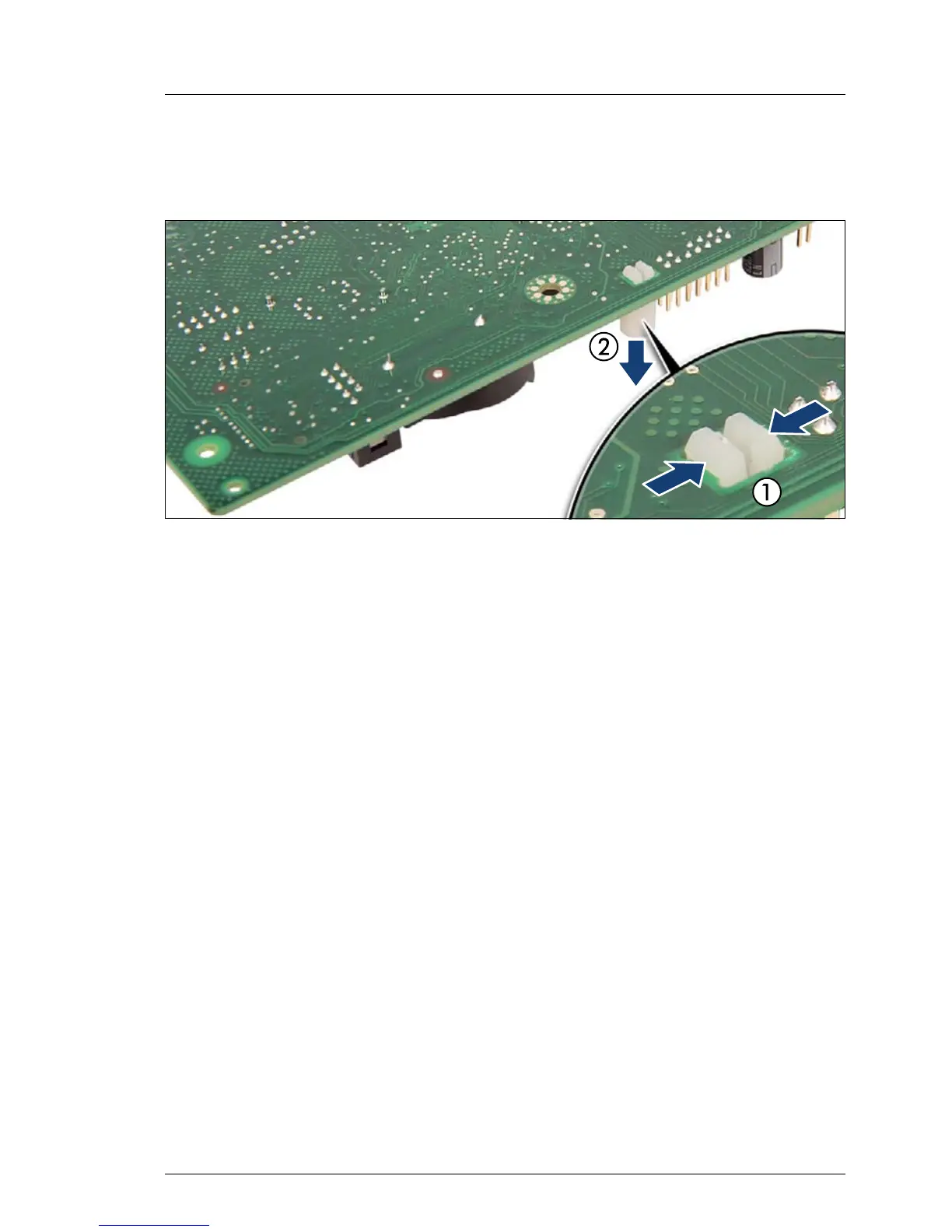
Figure 288: Removing the TPM spacer
Ê Using a small pair of combination pliers, press together the hooks on the
TPM spacer (1, see close-up) and remove it from the system board (2).
I If the TPM module is to be replaced, the TPM spacer may remain on
the system board.
14.3.2.4 Concluding steps
Perform the following procedures to complete the task:
Ê Close the side / top cover as described in section "Mounting the top cover"
on page 80 (rack server) or "Mounting the side cover" on page 85 (tower
server).
Ê When working on a rack-mounted server, secure it in the rack as described
in section "Sliding the server into the rack" on page 89.
If the server has been completely removed from the rack for maintenance
purposes, reinstall and secure it in the rack as described in section
"Mounting the server in the rack" on page 87.
Ê Reconnect the AC power cord to the power supply unit and secure it with a
cable tie as described in section "Connecting the server to the mains" on
page 90.
Ê If applicable, close the rack door as described in section "Closing the rack
door" on page 92.
 Loading...