EasyManuals Logo

Husqvarna TE 250 Workshop Manual

Husqvarna TE 250
470 pages
To Next Page IconTo Next Page
To Previous Page IconTo Previous Page
Page #104 background imageLoading...
Page #104 background image
F.4 Part. N. 8000 B0148 (02-2008)
ENGINE DISASSEMBLY
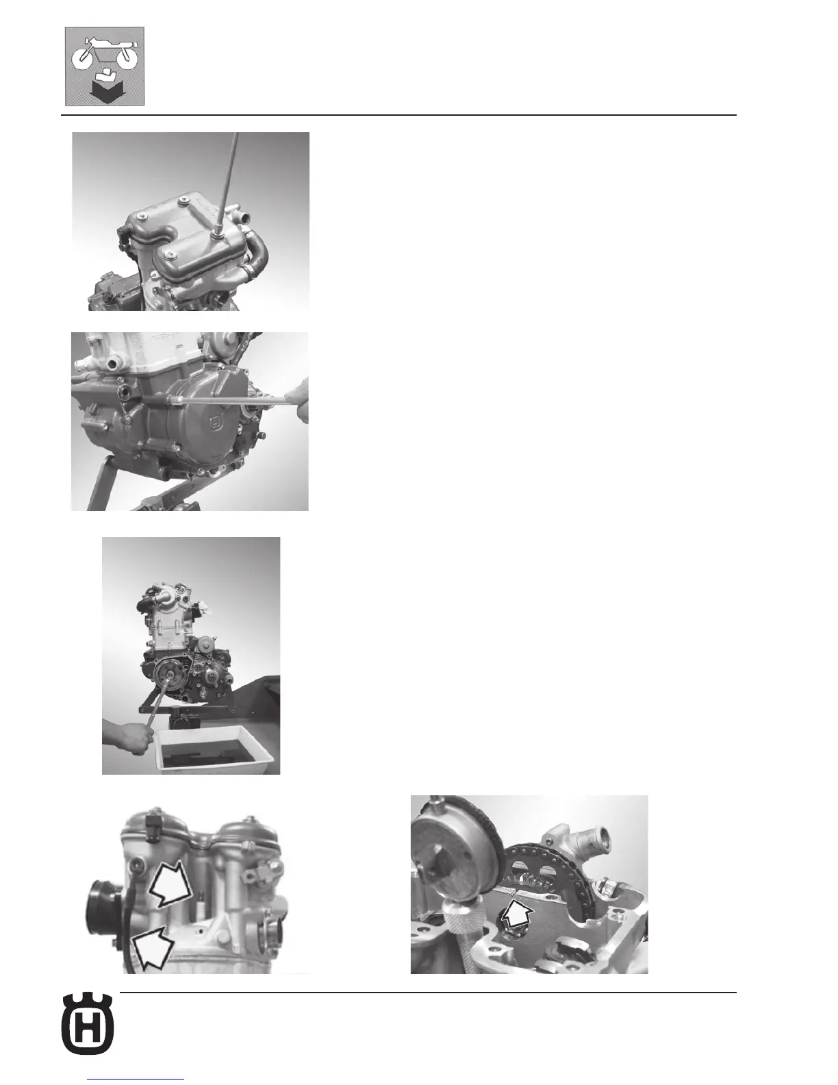
Cylinder head cover disassembly
Remove the four fastening screws (8 mm wrench) and the cylinder head cover
together with the relative gasket.
Camshaft disassembly
Remove the six fastening screws (8 mm wrench) and the alternator cover. Using
a 17mm wrench, position the piston at T.D.C. at the end of the compression stroke
(in this condition, the mark on the cylinder head is aligned with the two marks on
the idle gear of the camshafts, as shown in the figure on page F.7). Remove the
spark plug (16 mm wrench) and the lubrication hose from the cylinder head (13
mm wrench).

Table of Contents

Other manuals for Husqvarna TE 250

Questions and Answers:

Question and Answer IconNeed help?

Do you have a question about the Husqvarna TE 250 and is the answer not in the manual?

Husqvarna TE 250 Specifications

General IconGeneral
Displacement249 cc
Transmission6-speed
Cooling SystemLiquid
StarterElectric
Front SuspensionWP XPLOR 48
Front BrakeDisc brake
Rear BrakeDisc brake
Bore x Stroke66.4 mm x 72 mm
Engine Type2-Stroke

Related product manuals