I.36
Part. N. 8000 B0148 (02-2008)
FRONT SUSPENSION
25
34
34
28
33
27
30
26
31
32
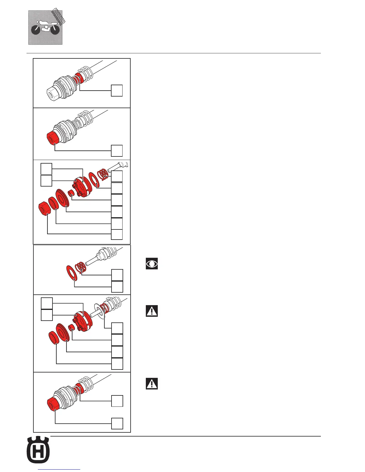
CHECKING THE REBOUND ADJUSTING UNIT
Dismantling
• Push the rebound spring back from the end part of the rod.
• Being very careful not to damage the washers, clamp the end of the rod (25) in the
vice, exploiting the 17 mm spanner’s grip and without over-tightening.
• With a 10 mm spanner, unscrew nut (34).
• In sequence, remove the nut (34) the calibrated spacer (28), the washer or the
washers’ stack which regulate rebound (33), the washer centering bush (27), the
piston (32) complete with segment (31), the by-pass washer or by-pass washers’
stack (30) and the spring (26).
Assembly
Washers (33) and piston (32) are responsible for the rebound braking.
Replacing washers (33) and piston (32) with other parts with different
characteristics, lets you change the fork behaviour during rebound if needed.
The by-pass washers (30) are responsible for rebound braking. Whenever
necessary, fork behaviour can be modifi ed during compression by replacing
the washers (30) with others having different features
WARNING
Use only Marzocchi original washers and pistons. Do notmodify the
components.
• Replace the piston segment (31) if needed.
• In the end part of the rod, fit the spring (26) and the washer or the by-pass washer
stack (30).
• Compress the spring and insert the following items in sequence: piston (32) with
its segment (31), the washer centring bushing (27), the washer or the washer stack
allowing to adjust extension (33), the calibrated spacer (28).
WARNING
As shown in the diagram, the piston (32) must bepositioned so that the
cylindrical part is opposite thewashers which regulate estension.
• Tighten the nut (34) by hand.
With a 10mm spanner, tighten the nut (34) to the required torque (see Table 5 -
Tightening torques).
• Remove the pumping element rod from the vice (25).
30
26
28
33
27
26
31
32
25
34
 Loading...