I.43
Part. N. 8000 B0148 (02-2008)
FRONT SUSPENSION
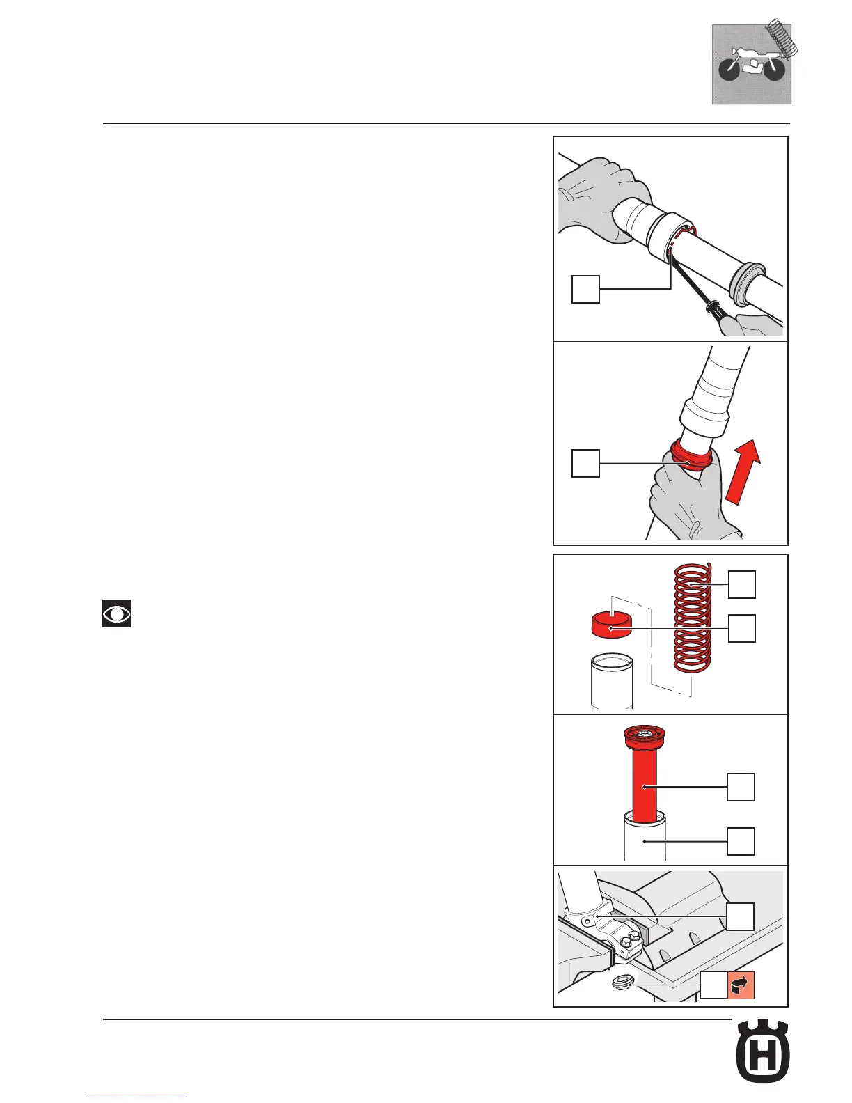
Mount the stop ring (15) using a small flat-tip screwdriver, checking it fits perfectly
into its groove and being a careful not to scratch the stanchion tube.
Re-assemble the dust seal (16) in its seat, pressing it home with your hands.
RE-ASSEMBLING THE CARTRIDGE
Insert the pre-load spacer (17) and the spring (19) inside the stanchion tube.
It is possible to modify the spring preload value by following the instructions
given in paragraph 5.2.
Insert the complete pumping unit (21) into the slider (11).
Clamp the fork leg in the vice by the wheel axle clamp (70).
Push the top cap so that the lower part of the cartridge comes out of the wheel axle
clamp.
Tighten the bottom nut (48) and fasten it at the required torque (see Table 5 -
Tightening torques) with a 21 mm socket wrench.

 Loading...