M.24 Part. N. 8000 B0148 (02-2008)
ELECTRIC SYSTEM, DIGITAL INSTRUMENT
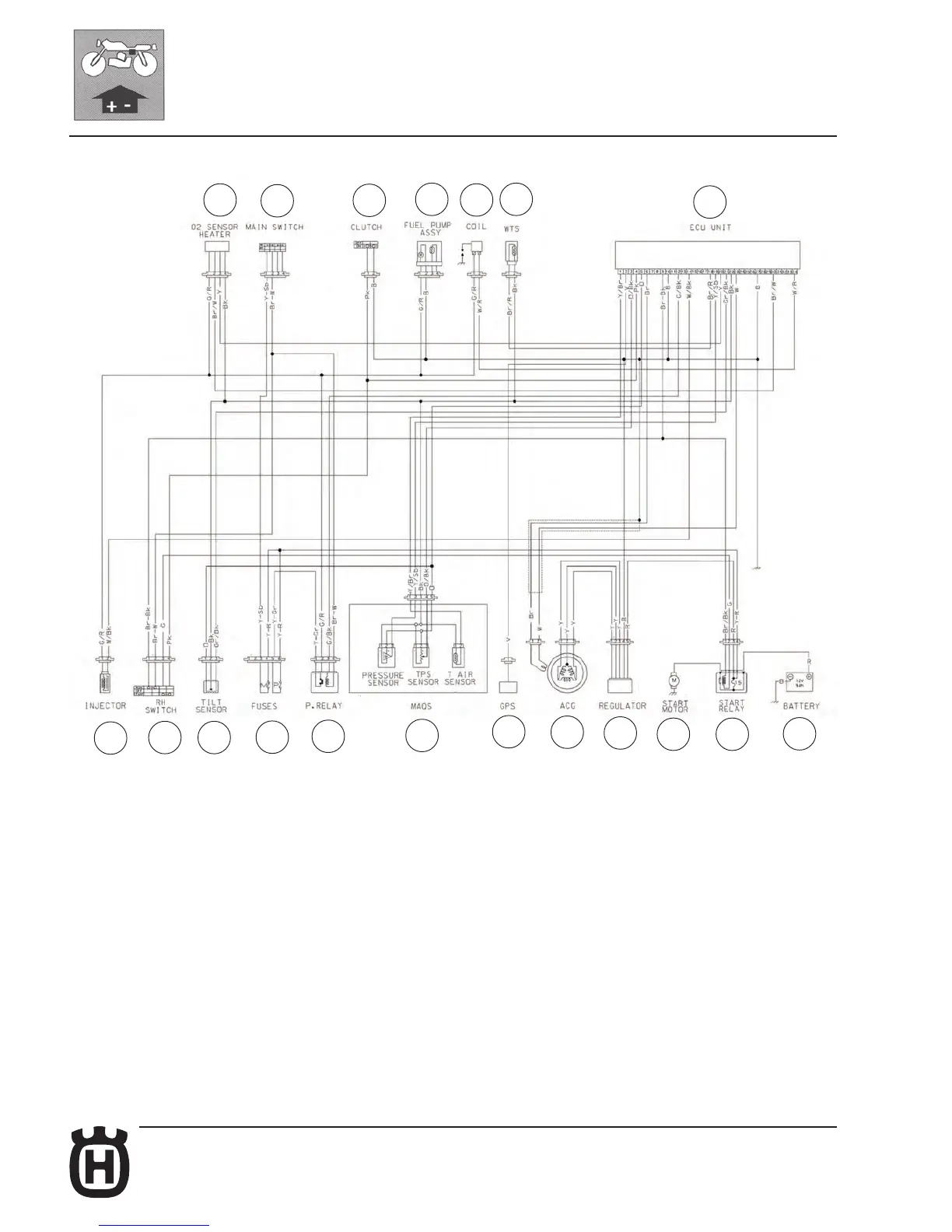
ELECTRONIC POWER UNIT WIRING DIAGRAM (ECU) (TE-SMR)
31
26
27
35
23
33
1
6
25 36
SMR
37
38
40
22
2
3
18 17
16
- Electronic power unit (1) (ECU);
- W.T.S. (33) (Water Temperature Sensor);
- Ignition coil (23);
- Fuel pump (35);
- Clutch switch (27);
- Ignition switch (26);
- O2 sensor heater (31);
- Battery (16);
- Electric start remote control switch (17);
- Starting motor (18);
- Voltage regulator-rectifier (3);
- Alternator (2);
- Gear shift position sensor (22);
- M.A.Q.S. (40) (pressure sensor +TPS sensor + air temperature sensor);
- Power relay (38);
- Fuse (37);
- R.H. switch (25);
- Injector (6);
- Fall sensor (36) (SMR).
 Loading...