I.6
Part. N. 8000 B0148 (02-2008)
FRONT SUSPENSION
84
93 42
03 13
27
5
31
91 12 52 37 82382
9
21
33
33
07
14
17
43
63
01
73
34
54
64
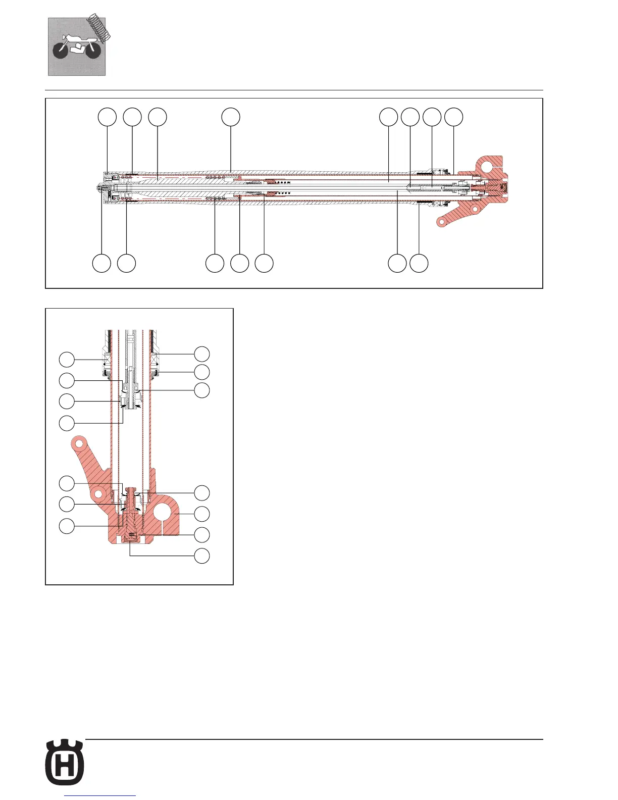
COMPONENTS OF THE FORK
The fork is based on a multivalve damping system that is exactly the same on both
fork’s legs. Each fork’s leg is therefore a complete suspension system which you
must refer to when adjusting any part of the fork.
5) Stanchi on tube
8) Lower sliding bushing
9) Spri ng cup
10) Oil seal
12) Dust seal
13) Outer slider
19) Compression adjustment screw
21) Spri ng
24) Spri ng gui de
25) Pre- load tube
28) Foot buffer
30) Cartridge body
31) Inner rod
32) Pumping element rod
33) Washers recall spring
34) Rebound piston washer
36) Pumping element piston
37) Rebound damping piston washers stack
39) Upper sliding bushing
41) Bottom valve
43) Compression valve washer
45) Bottom valve piston
46) Compression damping piston washers’ stack
48) Cap
70) Wheel axle clamp
71) Rebound adjustment screw
72) Conic pin
73) Body cap
In order to better understand how the fork works, in the figure here beside the moving
parts holding the wheel are indicated with different colours (background highlighted)
from those that remain fixed to the motorcycle frame (light background).
 Loading...