R.11Part. N. 8000 B0148 (02-2008)
SMR 450-R
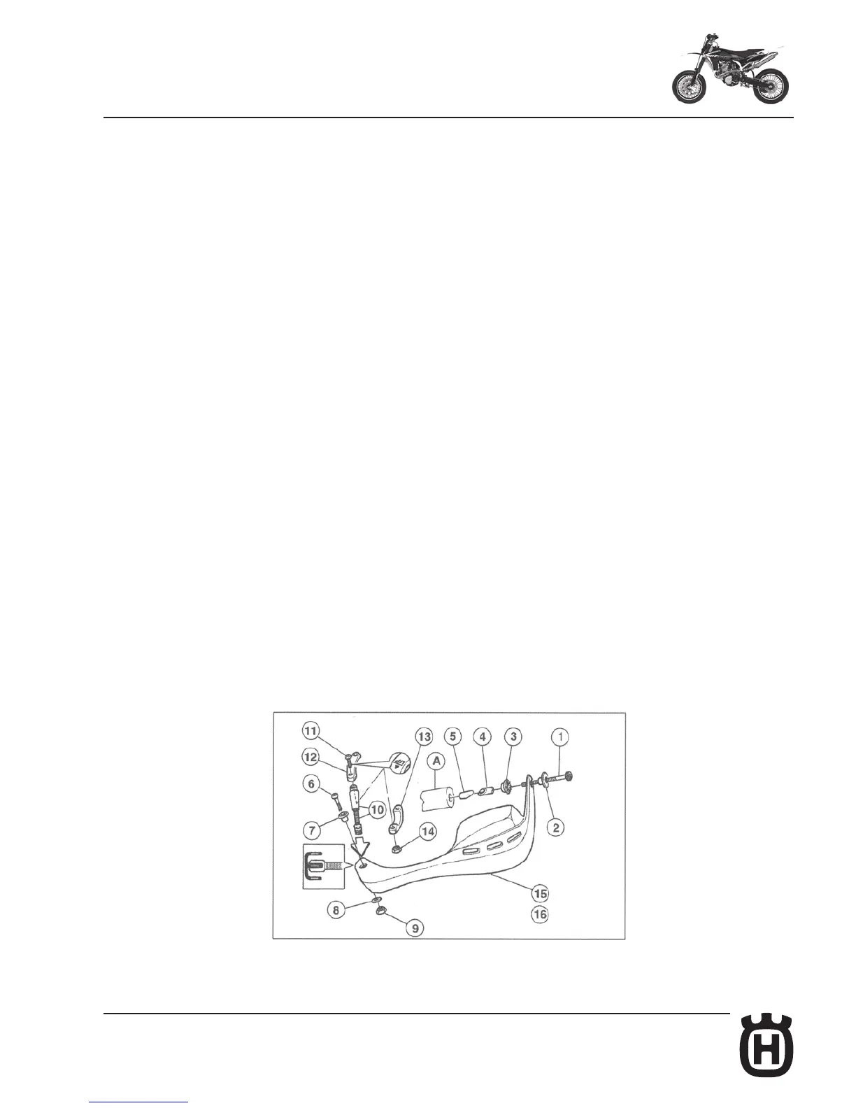
Assembling instructions for hand-guards kit
The kit consists of:
1- Screw M8x55 (2)
2- Collared bush (2)
3- Notched bush (2)
4- Spacer (2)
5- Threaded spacer (2)
6- Screw M6x40 (2)
7- Bush (2)
8- Washer (2)
9- Self-locking nut M6 (2)
10- Front tie rod (2)
11- Screw M6x30 (4)
12- Upper handlebar clamp (2)
13- Lower handlebar clamp (2)
14- Self-locking nut M6 (4)
15- Left hand guard (1)
16- Right hand guard (1)
Insert in the handlebar, final zone (A), these parts: threaded spacer (5), spacer
(4), notched bush (3), hand guard (15), collared bush (2) and screw (1) WITH-
OUT tighten it completely.
Assemble: the two clamps (12) and (13) on the handlebar (pay attention to the
upper clamp: it is identified with a mark "UP" and an "ARROW" that shows the
direction of march of the motorcycle) then the rear screw WITHOUT tighten it
completely.
Assemble: the front tie rod (10) on the guard (15) using the screw (6), the tie rod
on the handlebar clamps, front side, WITHOUT locking the screw (11) com-
pletely.
Now adjust all the hand guard assembly, then tighten completely FIRST the
clamps front screw, THEN the clamps rear screw and the side screw (1).
NOTE: the drawing shows the L.H. guard assembly, the R.H. guard assembly is
symmetrical.

 Loading...