M.18 Part. N. 8000 B0148 (02-2008)
ELECTRIC SYSTEM, DIGITAL INSTRUMENT
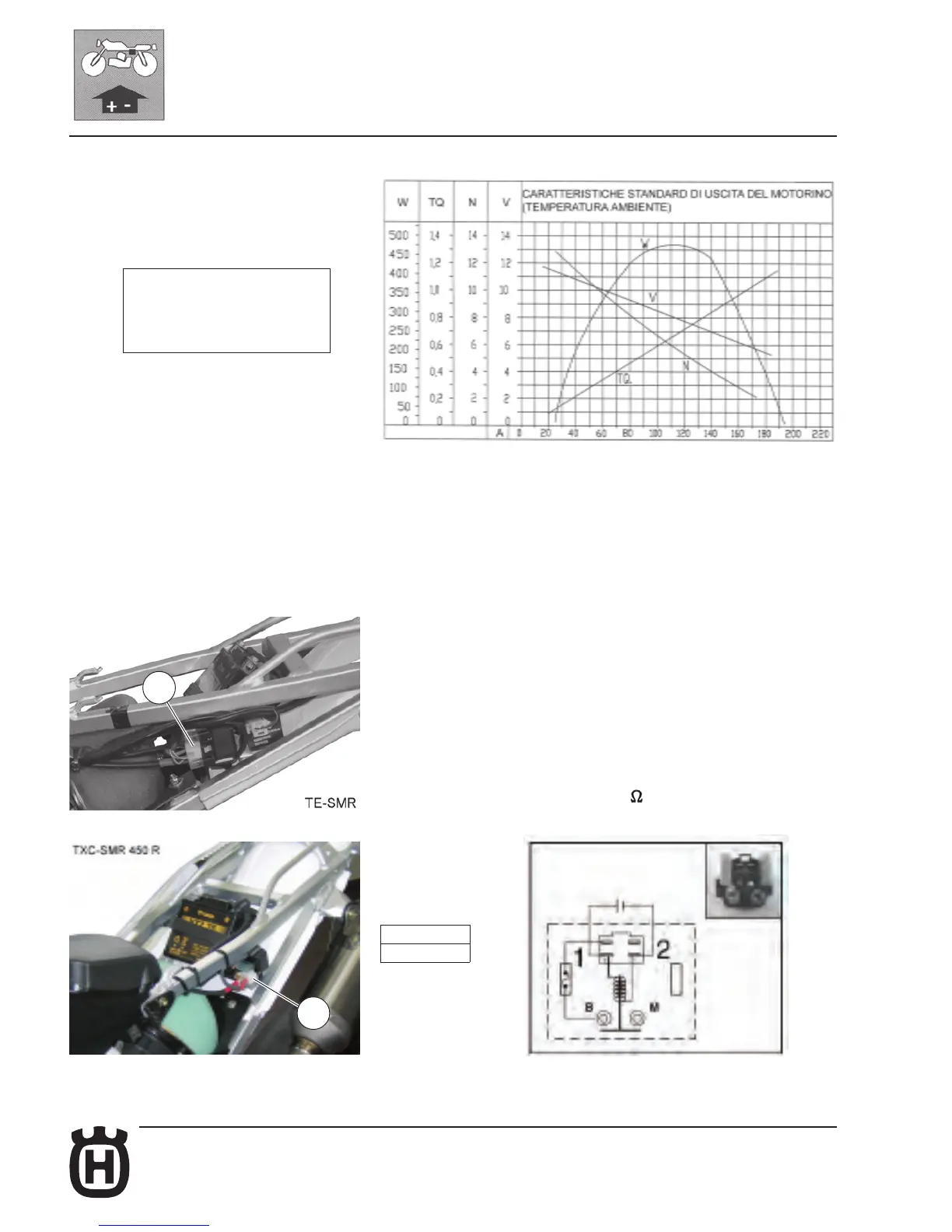
Starter motor test diagram
Starter motor maintenance
Maintenance operations on the starter motor involve checking the brushes for
wear, that the stator and rotor do not touch, and that they are correctky insu-
lated. It is advisable to carefully lubricate the motor's moving parts with "AGIP
F.1 GREASE" grease.
ELECTRIC START REMOTE CONTROL
SWITCH WIRING DIAGRAM
Electric start remote control switch check (TE-SMR-TXC)
Disconnect the starter relay coupling (A). Disconnect the cables from the positive
and negative poles of the battery to avoid short circuits during assembly.
Disconnect the cables of the starter motor and the positive cable of the battery
from the relay. Apply 12 volts to the terminals (1) and (2) of the relay and check
the continuity between terminals B-M.
Do not apply the battery voltage to the starter relay for more than five
seconds to avoid overheating and therefore damaging the winding. Using
a multi-tester, check that the winding is on open circuit or if a resistance is present.
The winding is in good condition if the value of the resistance revealed is as
indicated.
Multi-tester dial indication: Ohm
Starter relay resistance. Standard: 3 – 6 .
1- Output (W)
2- Torque (TQ)
3- Revolution (N: r.p.m. x 1000)
4- Terminal voltage (V)
5- Load current (A)
1= GROUND
2= + 12 v
A
A

 Loading...