I.18
Part. N. 8000 B0148 (02-2008)
FRONT SUSPENSION
11
21
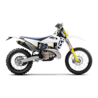
• Mount the stop ring ( 11 ) using a small flat- tip screwdriver, checking it fits perfectly
into its groove and being very careful not to scratch the stanchion tube.
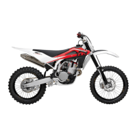
• Re- assemble the dust seal ( 12 ) in its seat, pressing it home with your hands.
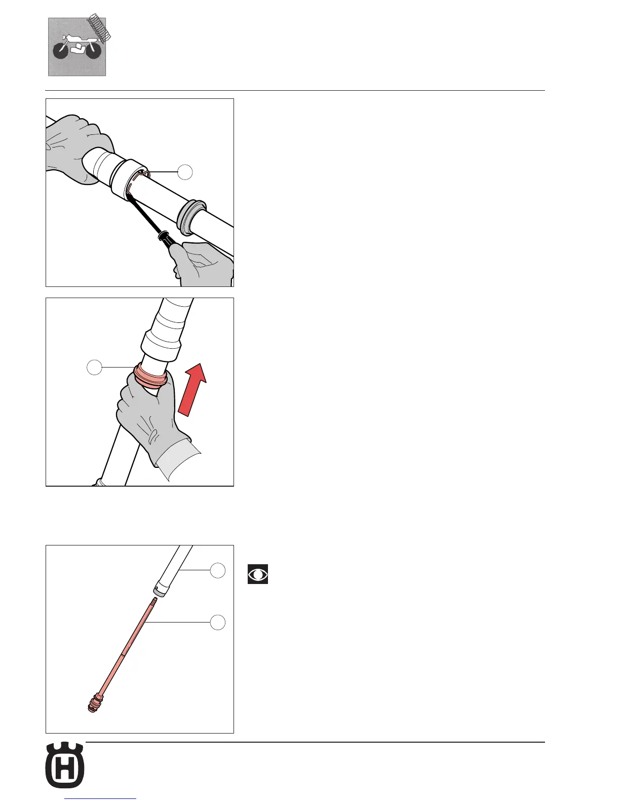
RE- ASSEMBLING THE PUMPING ELEMENT UNIT AND THE BOTTOM VALVE
• Insert the pumping element rod ( 32 ) into the body ( 30 )
In both pumping elements there is a sealing segment; before the assembling
make sure that it is not worn or damaged. Replace if necessary. Take great
care and if necessary use a small flat- tip screwdriver to help the pumping
element
piston into the sleeve. Insert the piston without any interference.
03
23

 Loading...