14. MALFUNCTION CODE Field Service Ver. 2.0 Jun. 2010
134
bizhub 164
TROUBLESHOOTING
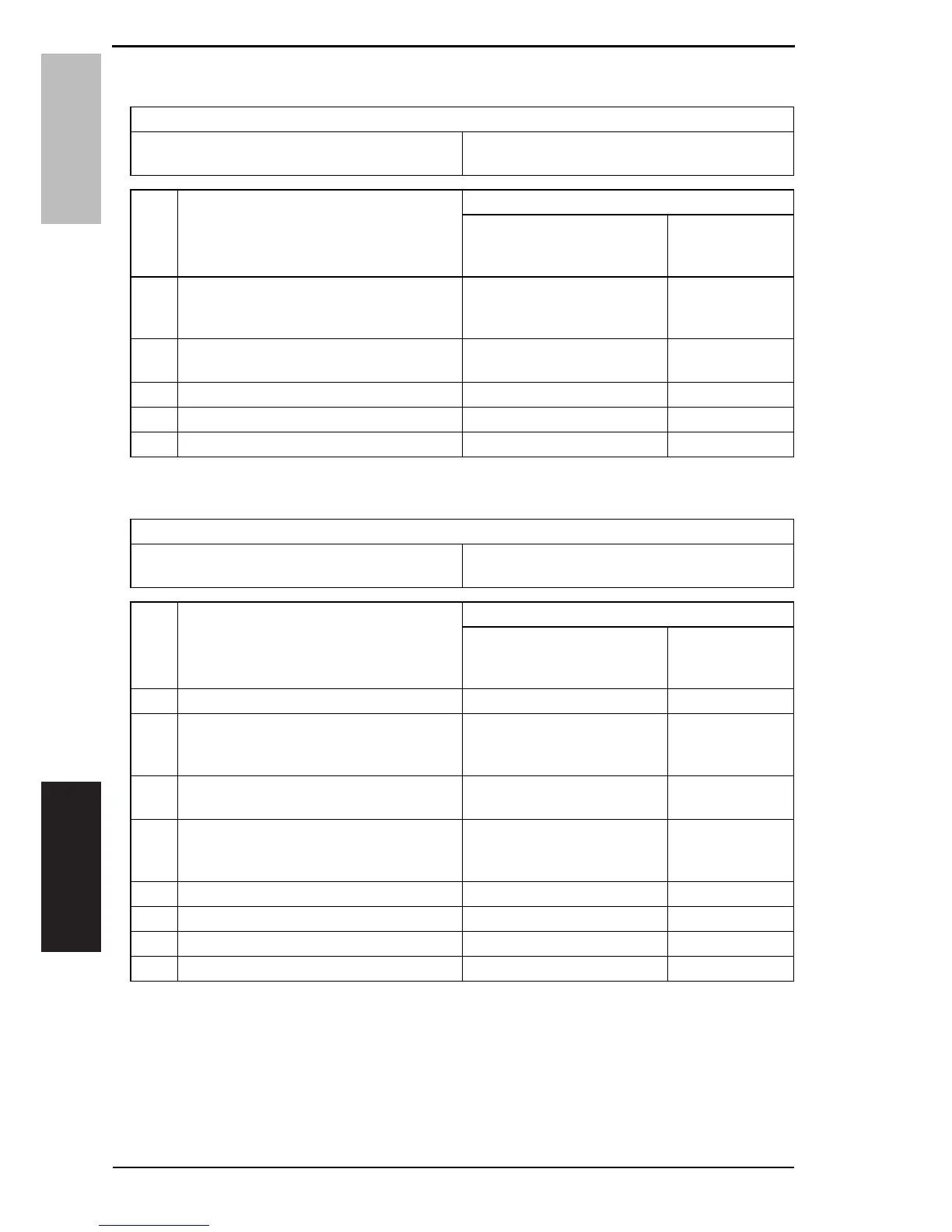
14.3.13 C5102: Main motor malfunction
14.3.14 C6101: Scanner home detection failure
Relevant electrical components
Main motor (M1) Printer control board (PRCB)
DC power supply (DCPU)
Step Operations
WIRING DIAGRAM
Control signal
Location
(Electrical compo-
nents)
1Check the connector between M1-PRCB
CN6 for proper connection and correct as
necessary.
--
2Check M1 for correct drive coupling and
correct as necessary.
--
3M1 operation check. PRCB CN6-7 (LOCK) D-9
4Change PRCB. - -
5Change DCPU. - -
Relevant electrical components
Scanner motor (M4)
CIS module (CIS)
Printer control board (PRCB)
Step Operations
WIRING DIAGRAM
Control signal
Location
(Electrical compo-
nents)
1Turn OFF and ON the power switch. – –
2Check the connector between M4-PRCB
P101 for proper connection and correct as
necessary.
––
3Check M4 for correct drive coupling and
correct as necessary.
––
4Check the connector between CIS-PRCB
P102 for proper connection and correct as
necessary.
––
5M4 operation check PRCB P101-1 to 4 F-11
6Change M4. – –
7Change CIS – –
8Change MFPB. – –

 Loading...