2GN/2GP/2GR-6
1-2-11
1-2-3 Installing the key counter (option)
Installing the key counter requires the following component:
Key counter (P/N 3025418011)
Key counter set (P/N 302A369708)
Supplied parts of key counter set:
Key counter socket assembly (P/N 3029236241)
Key counter cover (P/N 3066060011)
Key counter mount (P/N 3066060041)
Key counter retainer (P/N 302GR03020)
Key counter cover retainer (P/N 302GR03010)
One (1) M3 × 8 tap-tight P screw (P/N 5MBTPB3008PW++R)
Two (2) M4 × 10 tap-tight P screws (P/N 5MBTPB4010PW++R)
Two (2) M4 × 10 tap-tight S screws (P/N 5MBTPB4010TW++R)
Two (2) M3 × 6 bronze flat-head screws (P/N 7BB003306H)
One (1) M4 × 20 tap-tight S screw (P/N 7BB100420H)
One (1) M3 bronze nut (P/N 7BC1003055++H01)
One (1) M3 × 8 bronze binding screw (P/N B1B03080)
One (1) M4 × 30 tap-tight S screw (P/N B1B54300)
Five (5) M4 × 6 chrome TP screws (P/N B4A04060)
Two (2) M4 × 10 chrome TP screws (P/N B4A04100)
Procedure
1. Press the power key on the operation panel
to off. Make sure that the power indicator
and the memory indicator are off before
turning off the main power switch. And then
unplug the power cable from the wall outlet.
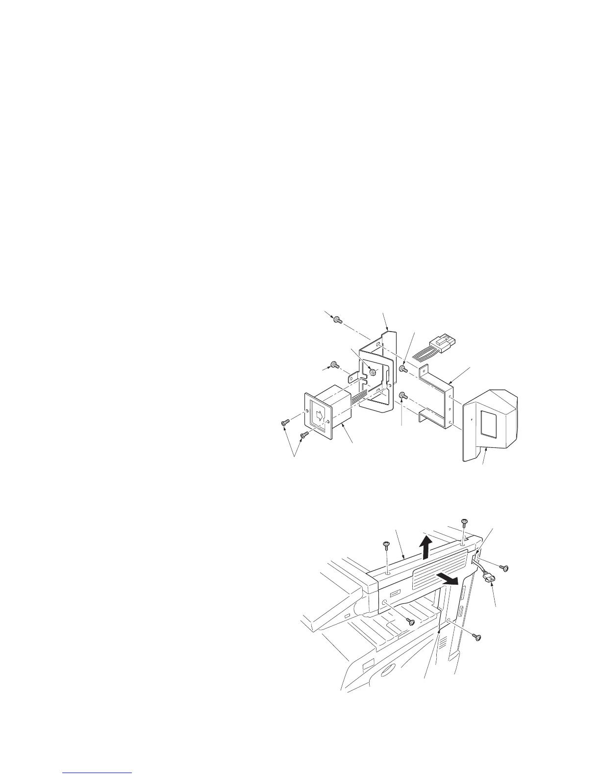
2. Fit the key counter socket assembly to the
key counter retainer using the two screws
and nut.
3. Fit the key counter mount to the key counter
cover using the two screws, and attach the
key counter retainer to the mount using the
two screws.
Figure 1-2-16
4. Remove the scanner right cover and the
upper right cover.
5. Cut out the aperture plate on the upper right
cover using nippers.
6. Pass the connecter of the machine through
the aperture and refit the upper right cover.
Figure 1-2-17
M3 x 6 flat-head
screws
(7BB003306H)
Key counter
mount
(3066060041)
Key counter cover
(3066060011)
M4 x 6 screw
(B4A04060)
M4 x 6 screw
(B4A04060)
Key counter
socket assembly
(3029236241)
M4 x 6 screw
(B4A04060)
M3 nut
(7BC1003055++H01)
Key counter retainer
(302GR03020)
M4 x 6 screw
(B4A04060)
Connecto
Upper right cover
Scanner right cover
Aperture

 Loading...