Miscellaneous Interfaces
Jetson AGX Xavier Series Product DG-09840-001_v2.5 | 108
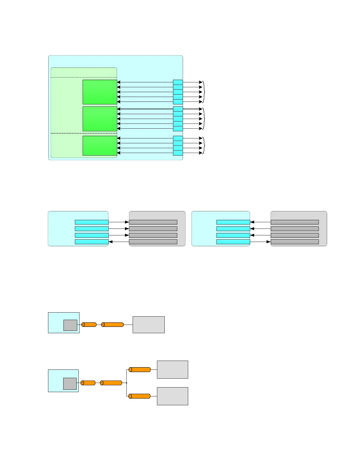
Figure 13-2. SPI Connections
Jetson AGX Xavier
SoC – SPI
SPI1_SCK
SPI1_MISO
SPI1_MOSI
SPI1_CS0_N
SPI1_CS1_N
UART
SP I 1_ C LK
SP I 1_M ISO
SP I 1_M OSI
SPI1_CS0_N
SPI1_CS1_N
SP I 3_ C LK
SP I 3_M ISO
SP I 3_M OSI
SPI3_CS0_N
SPI3_CS1_N
SP I 2_ C LK
SP I 2_M ISO
SP I 2_M OSI
SP I 2_CS0 #
SPI2_SCK
SPI2_MISO
SPI2_MOSI
SPI2_CS0_N
Routed to PCIe x16 connector on carrier board.
Alternately a vaila ble for general SPI usage.
JA Xi only: Route d to Saf ety MCU if
implemented in design.
J57
SPI3_SCK
SPI3_MISO
SPI3_MOSI
SPI3_CS0_N
SPI3_CS1_N
Not used on carrier board.
Available for general SPI usage.
AO
A56
D55
E55
E61
D62
F60
D60
F55
D56
G56
C57
E56
B5 6
Routed on carrier board to Expansion Connector
thro ugh selec ta bl e voltage leve l s hifte r (1 .8 V o r 3. 3V)
The following figure shows the basic SPI connections.
Figure 13-3. Basic SPI Master and Slave Connections
Jetson AGX Xavier
Master
SPIn_CSx#
SP I n_ SCK
SP I n_ MO SI
SP I n_ MISO
SPI Slave Device
CS (Chip Select)
CLK ( Clock)
MOSI (Master out, Sla ve in)
MISO (Ma ster in, Slave out)
Jetson AGX Xavier
Master
SPIn_CSx#
SP I n_ SCK
SP I n_
MOSI
SP I n_
MISO
SPI Master Device
CS (Chip Select)
CLK ( Clock)
MOSI (Master out, Sla ve in)
MISO (Ma ster in, Slave out)
13.2.1 SPI Design Guidelines
The following figures show the SPI topologies.
Figure 13-4. SPI Point-Point Topology
Module
SPI
Device
Main trunk
Die
PK G
Figure 13-5. SPI Star Topologies
Module
SPI
Device #1
Main trunk
SPI
Device #2
Die
PK G
Branch-A
Branch-B

 Loading...


