Display
Jetson AGX Xavier Series Product DG-09840-001_v2.5 | 69
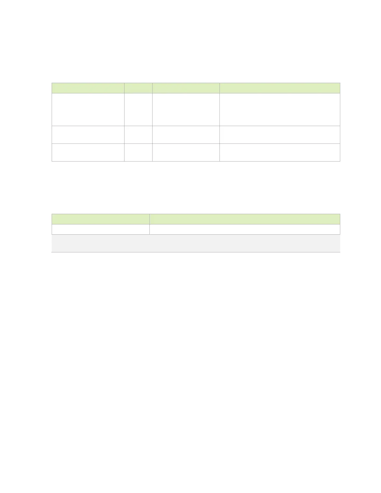
Table 9-4. DP and eDP Signal Connections
Module Pin Name Type Termination Description
HDMI_DPx_TX[3:0]_P/N O Series 0.1uF capacitors
on all lines
DP/eDP Differential CLK/Data Lanes: Connect
to matching pins on display connector. See
DP/HDMI Pin Mapping and connection
diagram for details.
DPx_AUX_CH_P/N I/OD Series 0.1uF capacitors DP/eDP: Auxiliary Channels: Connect to
AUX_CH+/– on display connector.
DPx_HPD I DP/eDP: Hot Plug Detect: Connect to HPD pin
on display connector.
Table 9-5. Recommended DP and eDP Observation Test Points for Initial
Boards
Test Points Recommended Location
One for each signal line. Near display connector. Connector pins can be used if accessible.
Note: Test points must be done carefully to minimize signal integrity impact. Avoid stubs and keep pads small
and near signal traces
9.2 HDMI
A standard DP 1.2a or HDMI v2.0 interface is supported. These share the same set of interface
pins, so either DisplayPort or HDMI can be supported natively.

 Loading...


