Main Connector Details
Jetson AGX Xavier Series Product DG-09840-001_v2.5 | 10
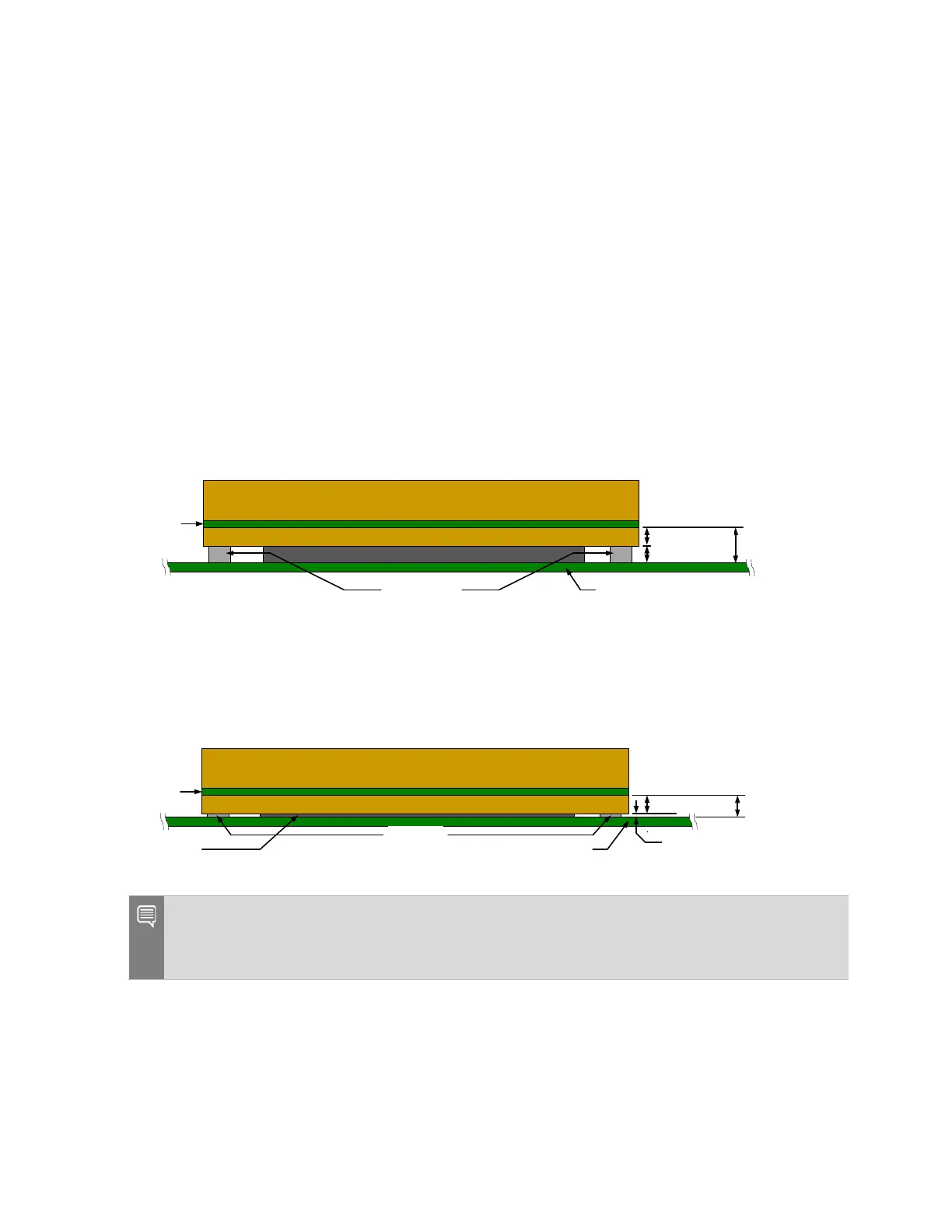
3.2 Module to Carrier Board Spacing
Details
The spacing between the module PCB and the carrier board PCB are shown in the following
figures for the following two cases:
5.5 mm connector on the carrier board (8mm nominal spacing)
2.5 mm connector (5 mm nominal spacing).
The standoffs to support the module are located between the carrier board and the bottom
plate.
Figure 3-3. 5.5 mm Height on Carrier Board – Molex Part # 2034560003
Connector
Module (TTM)
Module Bottom Plate
Module
PCB
Carrier Board PCB
Standoffs
8.00+/-0.15mm
See Note
4.00+/
-0.2mm
Figure 3-4. 2.5 mm Height on Carrier Board – Molex Part # 2048430001
Module (TTM)
Module Bottom Plate
Module
PCB
Carrier Board PCB
Washers
See Note
Connector
5.00+/-0.15mm
4.00+/-0.2mm
Notes: See Section 3.3 on recommendations for standoff heights.
If the Molex Part # 2048430001, 2.5 mm height connector is used, there can be no components
under the module on the carrier board due to the extremely limited clearance.

 Loading...


