Main Connector Details
Jetson AGX Xavier Series Product DG-09840-001_v2.5 | 11
3.3 Module to Carrier Board Standoff
Height Recommendations
Standoffs/Spacers are required between the module bottom plate and the carrier board. The
height should be chosen to accommodate the tolerances in the bottom plate and connector
mating heights as well as the standoff itself. If the standoff is too short, the carrier board PCB
may warp as the mounting screws are tightened. The two cases (5.5 mm and 2.5 mm
connector on carrier board) are described in this section and are followed with tables that
show the possible permutations of tolerances across the three items involved. (bottom plate,
mated connectors, and spacers). The platform designer can determine if a different height
would be more appropriate but should consider both the PCB warpage (standoff height too
short) and sweep range to find the best balance.
The following examples are based on Molex parts using spacer heights and spacer tolerances
to produce a workable solution.
Molex Part # 2034560003 (5.5 mm height – 8.00+/-0.15 mm board to board spacing) case
For this case, a standoff height of 4.5 mm is recommended. This is based on a standoff with
±0.13 mm height tolerance. The tolerance for the bottom plate is ±0.2 mm and for mated
connectors the tolerance is ±0.15 mm.
Table 3-1 shows example calculations using the connector board spacing, module bottom
plate height and recommended standoff height with tolerances mentioned.
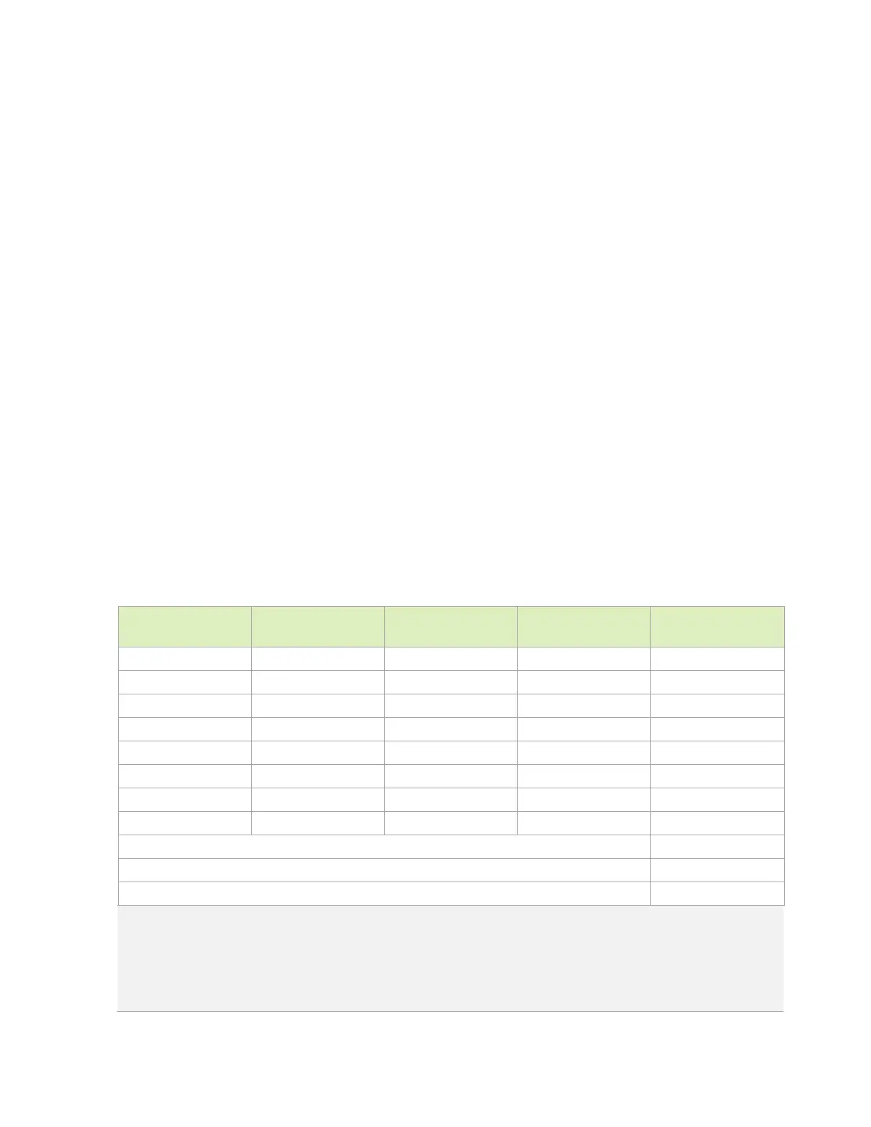
Table 3-1. Standoff Height Calculations for 5.5 mm Height Connector Case
Board to Board
Spacing (mm)
Bottom Plate Height
(mm)
Gap (mm) Standoff Height Board to Board
Spacing (mm)
7.85 3.8 4.05 4.37 0.32
7.85 3.8 4.05 4.63 0.58
7.85 4.2 3.65 4.37 0.72
7.85 4.2 3.65 4.63 0.98
8.15 3.8 4.35 4.37 0.02
8.15 3.8 4.35 4.63 0.28
8.15 4.2 3.95 4.37 0.42
8.15 4.2 3.95 4.63 0.68
Connector sweep range 1.5
Min to Max sweep usage 0.98
Remaining sweep 0.52
Notes:
1. Positive values mean no PCB warpage but less sweep. Negative values can result in PCB warpage.
2. The mating connector height tolerance comes from the Molex connector specification.
3. The connector contact sweep range can be found on the Molex website in the Mirror Mezz area.
4. The module bottom plate height/tolerance can be found in the
Jetson AGX Xavier Data Sheet
.

 Loading...


