Gigabit Ethernet
Jetson AGX Xavier Series Product DG-09840-001_v2.5 | 62
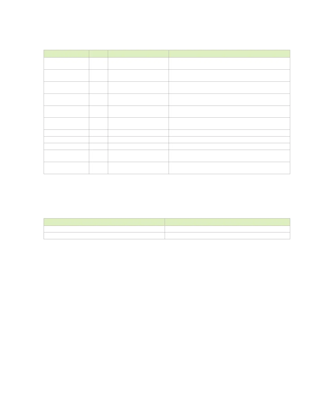
Table 8-4. Ethernet Signal Connections
Module Pin Name Type Termination Description
O
RGMI Transmit Clock: Connect to TXCLK pin on GbE
Transceiver.
O
RGMI Transmit Data: Connect to TXD[3:0] pins on GbE
Transceiver.
O
RGMI Transmit Control: Connect to TXEN pin on GbE
Transceiver.
I
RGMI Receive Clock: Connect to RXCLK pin on GbE
Transceiver.
I
RGMI Receive Data: Connect to RXD[3:0] pins on GbE
Transceiver.
I
RGMI Receive Control: Connect to RXDV pin on GbE
Transceiver.
O
MDC: Connect to MDC pin on GbE Transceiver.
I/O 2.2kΩ pull-up to VDD_1V8
MDIO: Connect to MDIO pin on GbE Transceiver.
O
Ethernet Reset: Connect to Reset input on Ethernet PHY.
I 10kΩ pull-up to VDD_1V8
Ethernet Interrupt: Connect to Interrupt output on Ethernet
PHY.
DIFF
I/O
ESD device to GND per signal
Gigabit Ethernet MDI IF Pairs: Connect to Magnetics
+/–
pins
Table 8-5. Recommended Gigabit Ethernet Observation Test Points for
Initial Boards
Test Points Recommended Location
One for each of the RGMII lines.
One for each of the
lines. Near Jetson AGX Xavier connector and magnetics device.

 Loading...


