Miscellaneous Interfaces
Jetson AGX Xavier Series Product DG-09840-001_v2.5 | 113
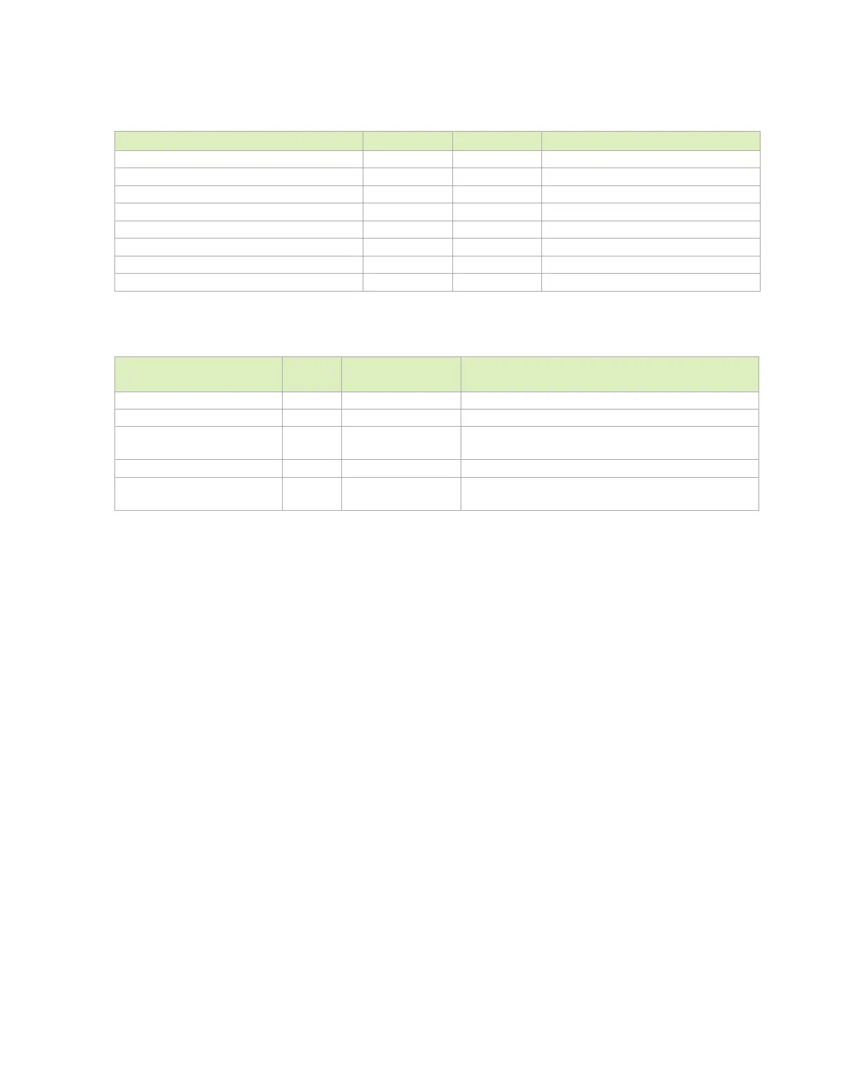
Table 13-14. CAN Interface Signal Routing Requirements
Parameter Requirement Units Notes
Max Data Rate / Frequency 5 Mbps / MHz
Configuration / Device Organization 1 load
Reference plane GND
Trace Impedance 50 Ω ±15%
Via proximity (Signal via to GND return via) < 3.8 (24) mm (ps)
Trace spacing - Microstrip / Stripline 4x / 3x dielectric
Max Trace Length (for RX and TX only) 310 (1950) mm (ps)
Max Trace Length/Delay Skew from RX to TX 8 (50) mm (ps)
Table 13-15. CAN Signal Connections
Module Pin Name
(Function)
Type Termination Description
O
CAN Data Output: Connect to matching pin of device
I
CAN Input: Connect to Peripheral pin of device
GPIO06 (CAN0_EN)
GPIO09 (CAN1_EN)
O
CAN Enable: Connect to matching pin of device
O
CAN 1 Standby: Connect to matching pin of device
GPIO07 (CAN0_WAKE)
GPIO10 (CAN1_WAKE)
I
CAN Wake: Connect to matching pin of device

 Loading...


