Main Connector Details
Jetson AGX Xavier Series Product DG-09840-001_v2.5 | 12
Molex Part # 2048430001 (2.5 mm height – 5.00+/-0.15 mm board to board spacing) case
For this case, a standoff height of 1.5 mm is recommended. This is based on a standoff
(washer) with ±0.13 mm height tolerance. The tolerance for the bottom plate is ±0.2 mm and
for mated connectors the tolerance is ±0.15 mm. Note that washers may typically have
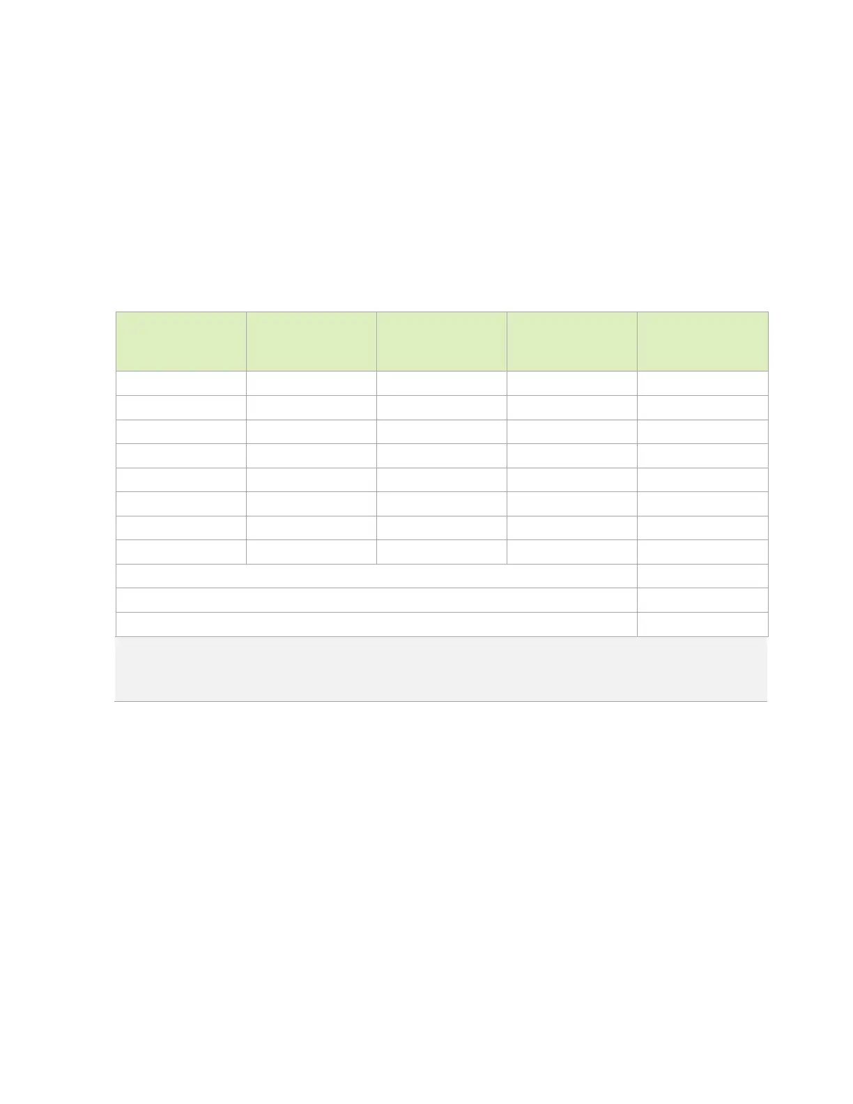
significantly larger tolerances which should be considered. Table 3-2 shows example
calculations using the connector board spacing, module bottom plate height and
recommended standoff/washer height with tolerances mentioned.
Table 3-2. Standoff Height Calculations for 2.5 mm Height Connector Case
Board to Board
Spacing (mm)
Bottom Plate
Height (mm)
Board to Bottom
Plate Gap (mm)
Standoff Height
(mm)
Space Beyond
Ideal Mating Spec.
(mm)
4.85 3.8 1.05 1.37 0.32
4.85 3.8 1.05 1.63 0.58
4.85 4.2 0.65 1.37 0.72
4.85 4.2 0.65 1.63 0.98
5.15 3.8 1.35 1.37 0.02
5.15 3.8 1.35 1.63 0.28
5.15 4.2 0.95 1.37 0.42
5.15 4.2 0.95 1.63 0.68
Connector sweep range (From Connector Spec) 1.5
Worst case space beyond the ideal connector mating case (from table above) 0.96
Remaining connector pin contact length 0.54
Notes:
1. Positive values mean no PCB warpage but less sweep. Negative values can result in PCB warpage.
2.
See additional notes in the “Notes” section of Table 3-1.
3.4 Module Installation and Removal
To install the Jetson AGX Xavier Series module correctly, follow the following sequence and
mounting hardware instructions:
1. Connectors should be parallel with respect to each other during mating.
2. Use a smooth motion during mating (no mechanical shock, knocking, hammering).
3. It will be ideal if push/pressure points are marked on the “B” side of the PCB for
operators.
4. The top and bottom PCB are to be bolted to enhance reliability.
5. Secure with M3 screws (4x) from the top of the module. Torque the screws to 2.5 lbf-in.

 Loading...


