Display
Jetson AGX Xavier Series Product DG-09840-001_v2.5 | 76
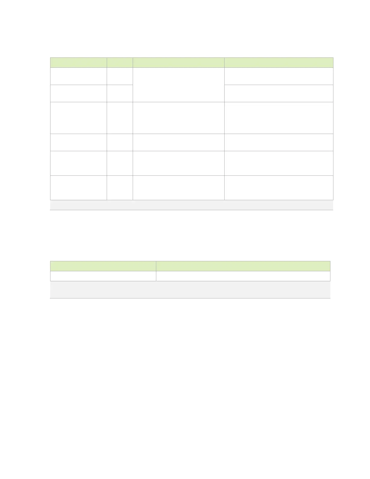
Table 9-7. HDMI Signal Connections
Module Pin Name Type Termination (See Note on ESD) Description
HDMI_DPx_TX3_N/P
DIFF
0.1uF series ACCAP → 500Ω RPD
(controlled by FET) → EMI/ESD (if
required),.≤6Ω RS (series resistor)
HDMI Differential Clock: Connect to C–/C+ and
HDMI_DPx_TX[2:0]_N/
P
DIFF
OUT
HDMI Differential Data: Connect to D[2:0]+/–
pins. See Table 9-2 and connection diagram.
DPx_HPD I
Jetson AGX Xavier to Connector: 10kΩ
PU to 1.8V → level shifter → 100kΩ
series resistor. 100kΩ to GND on
HDMI Hot Plug Detect: Connect to HPD pin on
HDMI Connector
HDMI_CEC I/OD
Gating circuitry, See connection figure
or reference schematics for details.
HDMI Consumer Electronics Control: Connect
to CEC on HDMI Connector through circuitry.
DPx_AUX_CH_N/P I/OD
From Jetson AGX Xavier to Connector:
10kΩ PU to 3.3V → level shifter →
1.8kΩ PU to 5V → connector pin
HDMI: DDC Interface – Clock and Data: Connect
DPx_AUX_CH+ to SCL and DPx_AUX_CH– to
HDMI 5V Supply P
Adequate decoupling (0.1uF and 10uF
recommended) on supply near
connector.
HDMI 5V supply to connector: Connect to +5V on
HDMI connector.
Note: Any ESD and/or EMI solutions must support targeted modes (frequencies).
Table 9-8. Recommended HDMI and DP Observation Test Points for Initial
Boards
Test Points Recommended Location
One for each signal line. Near display connector. Connector pins can be used if accessible.
Note: Test points must be done carefully to minimize signal integrity impact. Avoid stubs and keep pads small and near signal
traces.

 Loading...


