Gigabit Ethernet
Jetson AGX Xavier Series Product DG-09840-001_v2.5 | 61
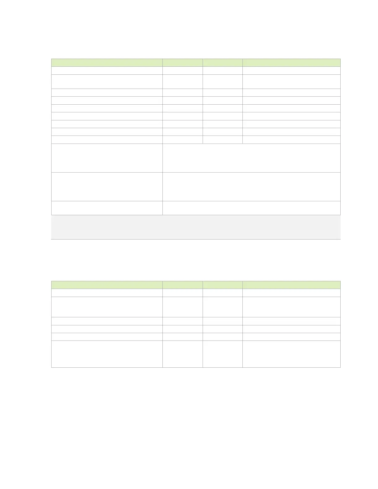
Table 8-2. RGMII Interface Signal Routing Requirements
Parameter Requirement Units Notes
Max Frequency 125 MHz
Topology Point to point
Unidirectional, source terminated, source
synchronous
Reference plane GND or PWR See note 1
Max PCB breakout delay 5 (30) mm (ps)
Trace Impedance 45-50 Ω ±15%
Via proximity (Signal via to GND return via) < 3.8 (24) mm (ps) See note 2
Trace spacing: Microstrip / Stripline
Max Trace Length/Delay 74 (463) mm (ps)
Max Trace Delay Skew Between Clock and Data 4.8 (30) mm (ps)
Isolation of TX and RX CLK signals One of the following options for
and
signals:
1.
shielding from each other and any other signal, or
2. >5x spacing from each other and any other signal, or
3.
Routed on separate layers from each other and any other signal
Isolation of TX and RX groups One of the following options for
signal and
signal groups:
1.
shielding from each other, or
2. >5x spacing from each other, or
3. Routed on separate layers from each other
Noise Coupling Avoidance
Keep critical traces away from other signal traces or unrelated power
traces/areas or power supply components
Notes:
1. If PWR, add 2x 0201 100nF and 2x 0402 4.7uF decoupling capacitors between PWR and GND for return current
2. Up to 4 signal vias can share a single GND return via
Table 8-3. Ethernet MDI Interface Signal Routing Requirements
Parameter Requirement Units Notes
Reference plane GND
Trace Impedance: Diff pair / Single Ended 100 / 50 Ω
±15%. Differential impedance target is
100Ω. 90Ω can be used if 100Ω is not
achievable
Min Trace Spacing (Pair-Pair) 0.763 mm
Max Within Pair (Intra-Pair) Skew 0.15 (1) mm (ps)
Number of Vias minimum
Ideally there should be no vias, but if
required for breakout to Ethernet controller
or magnetics, keep very close to either
device.

 Loading...


