Power
Jetson AGX Xavier Series Product DG-09840-001_v2.5 | 28
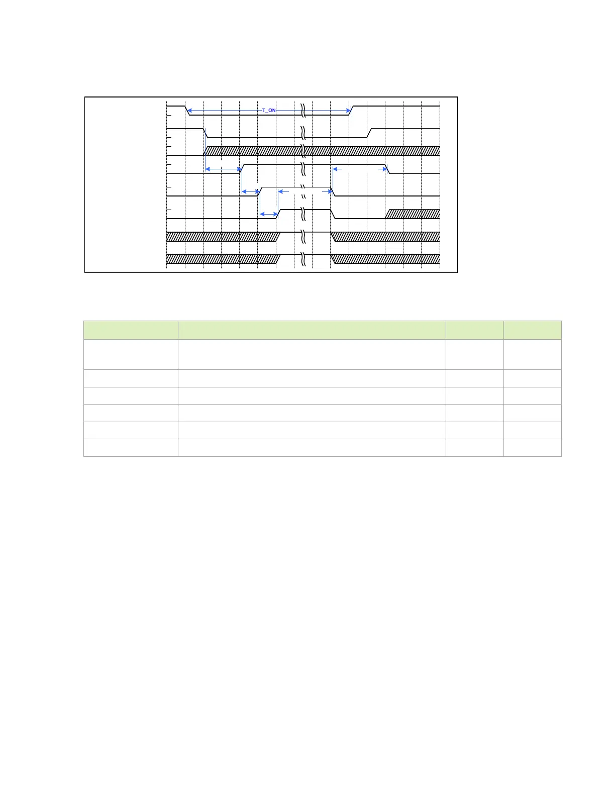
Figure 5-11. Power-On to OFF Power Button Held Low > 10 Seconds
MODULE_POWER_ON
BUTTON_POWER_ON*
CARRIER_POWER_ON
RESET_N
VIN_PWR_ON
POWER_BTN_ N
FORCE_SHUTDOWN_N
ACOK
T_ MP O
T_CPO
T_ VP WR _O N
T_VPWR_OFF1
T_MPO_OFF1
Table 5-7. Power-On to OFF Timing Power Button Held Low > 10 Seconds
Timing Parameter Typical Units
T_ON Power button active duration for forced OFF
(T_PWR_ON + T_MPO_ON + T_CPO + T_MPO_OFF1)
> 10 s
T_VPWR_ON Delay to first rail ON (de-bounce only) 20 ms
T_MPO_OFF1 Wait time to force MODULE_POWER_ON OFF 10 s
T_MPO_ON Enable delay from VIN_PWR_ON rising edge 80 ms
T_CPO Maximum allocated delay to detect CARRIER_POWER_ON 10 ms
T_VPWR_OFF1 Delay to first rail OFF 10 ms
5.5 Power Discharge
To meet the power down requirements, discharge circuitry is required. Figure 5-12 shows a
simplified version of what is in the P2822 Jetson AGX Xavier carrier board. The DISCHARGE
signal is generated, based on a transition of the
CARRIER_POWER_ON signal or the removal of
the main supply (
VDD_SRC). When DISCHARGE is asserted, the various carrier board rails that
need to be discharged are pulled to
GND. Removal of the VDD_SRC supply also causes
VDDIN_PWR_BAD_N to go active which causes Jetson AGX Xavier to initiate a controlled shut
down.
5.5.1 DV/Dt Circuit Considerations
The portion of the circuit that asserts VDDIN_PWR_BAD_N when power is removed is designed to
start the shutdown as soon as a voltage drop of ~0.5V is detected. This DV/Dt circuit helps to
provide more time to discharge the necessary rails before the module loses power. It is
recommended that the circuit be kept as shown to provide the most margin for properly
sequencing power off during sudden power removal cases. If the supply cannot maintain the

 Loading...


