Miscellaneous Interfaces
Jetson AGX Xavier Series Product DG-09840-001_v2.5 | 111
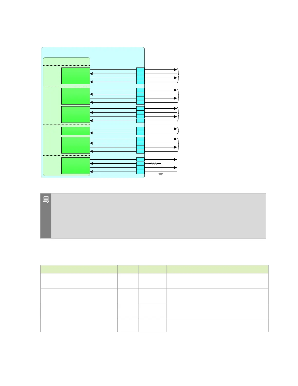
Figure 13-7. Jetson AGX Xavier UART Connections
Jetson AGX Xavier
SoC – UART
UART4_TX
UART4_RX
UART4_RTS
UART 4_CTS
CAM
(BOOT_SEL2 Strap) UART1_TX
UART 1_RX
(UFS_SEL Strap) UART1_RTS
UART 1_CTS
(RAM_CODE3 Strap) UART 2_TX
UART 2_RX
(RAM_CODE2 Strap) UART 2_RTS
UART 2_CTS
(RAM_CODE1 Strap) UART 5_TX
UART 5_RX
(RAM_CODE0 Strap) UART 5_RTS
UART 5_CTS
UART 3_TX_DEBUG
UART 3_RX_DEBUG
SP I 2_ C L K
SP I 2_M ISO
SP I 2_M OSI
SPI2_CS0_N
(BOOT_SEL1 Strap) UART4_TX
UART 4_RX (RSVD)
(BOOT_SEL0 Strap) UART4_RTS
UART 4_CTS
UART1_TX
UART1_RX
UART1_RTS
UART 1_CTS
UART2_TX
UART2_RX
UART2_RTS
UART 2_CTS
UART
Routed on carrier board to UART-USB Bridge
Used for Camera GPIO on carrier board
K53
CONN
Routed on carrier board to UART-USB Bridge
UART3_TX
UART3_RX
K54
L51
H54
J58
H58
L5
L48
L4
L49
K58
H57
C58
C56
G58
A57
H62
K60
AO
UART5_TX
UART5_RX
UART5_RTS
UART 5_CTS
Routed on carrier board to Expansion Connector
through se lecta ble volt age leve l s hifte r (1.8 V or 3. 3V)
Routed on carrier board to M.2 Key E Connector
Used for Camera GPIO on carrier board
Unused on carrier board – Available to use as GPIO
10 kΩ
SPI2_SCK
SPI2_MISO
SPI2_MOSI
SPI2_CS0
Routed to PCIe x16 connector on carrier board.
Alternately a vaila ble f or ge neral SPI usage or as
additional UART interface.
UART 7_TX ( UG3_TXD)
UART 7_RX (UG3_RXD)
UART 7_RTS (UG3_RTS)
UART 7_CTS (UG3_CTS)
E61
D62
F60
D60
Notes: UART4 pins do not support UART functionality and UART4_RX pin is reserved and must be
tied to GND through a 10 kΩ resistor. See the routing requirements in Table 13-12. UART4_TX,
UART4_RTS and UART4_CTS are available for use as GPIOs.
Care must be taken that any of the UART pins with straps associated with them are not pulled up
and down or driven up and down by connected devices that would affect the strap level at power-
on.
Table 13-11. UART Signal Connections
Module Pin Name Type Termination Description
UART[5,2:1]_TX, UART3_TX_DEBUG and
SPI2_CLK (UART7_TX)
O UART Transmit: Connect to Peripheral RXD pin of device
UART[5,2:1]_RX, UART3_RX_DEBUG and
SPI2_MISO (UART7_RX)
I UART Receive: Connect to Peripheral TXD pin of device
UART[5,2:1]_CTS and SPI2_CS0_N
(UART7_CTS)
I
UART Clear to Send: Connect to Peripheral RTS_N pin
of device
UART[5,2:1]_RTS and SPI2_MOSI
(UART7_RTS)
O
UART Request to Send: Connect to Peripheral CTS pin
of device

 Loading...


