Display
Jetson AGX Xavier Series Product DG-09840-001_v2.5 | 66
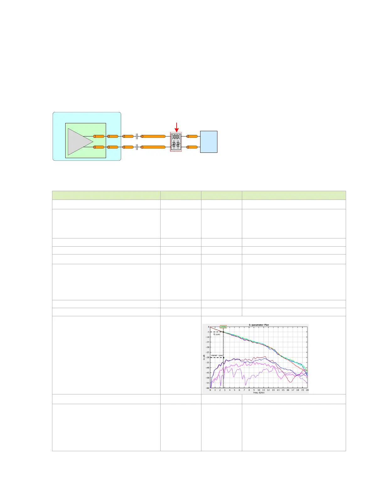
9.1.1 DP and eDP Routing Guidelines
Figure 9-2 shows the topology for DisplayPort and embedded DisplayPort. Table 9-3 shows the
signal routing requirements including DP_AUX.
Figure 9-2. DP and eDP Differential Main Link Topology
Module
eDP
Conn
SoC
Pkg
DP
Dri ve r
P
N
Com m on Mode
Cho kes & ES D
Table 9-3. DP and eDP Main Link Signal Routing Requirements
Parameter Requirement Units Notes
Max Data Rate / Min UI
HBR2
HBR
RBR
5.4 / 185
2.7 / 370
1.62 / 617
Gbps / ps
Per data lane
Number of Loads / Topology 1 load Point-Point, Differential, Unidirectional
Insertion Loss
E-HBR @ 0.675GHz
PBR 0.68GHz
HBR 1.35GHz
HBR2 @ 2.7GHz
<=0.7
<=0.7
<=1.2
<=2.4
dB
dB
dB
dB
Resonance dip frequency >8 GHz
TDR dip >85 Ω @ Tr-200ps (10%-90%)
FEXT
@ DC
@ 2.7GHz
<= -40dB
<= -30dB
IL/FEXT plot – up to HBR2
Trace Impedance (Diff pair) 100
90
85
Ω (±10%)
100Ω is the spec. target. 95/85Ω are
implementation options (Zdiff does not
account for trace coupling)
95Ω should be used to support DP-HDMI co-
layout as HDMI 2.0 requires 100Ω impedance
(see HDMI section for addition of series
resistor R
S).

 Loading...


