YH4
GRAND
VITARA
ANTILOCK BRAKE SYSTEM (ABS) (OPTIONAL) 5E1-27
1. ABS hydraulic unit/
control module assembly
2. ABS hydraulic unit/
control module
connector
1. ABS hydraulic
unit/ control
module connector
DTC 57 (DTC C1057)– SOLENOID AND PUMP MOTOR POWER SOURCE
CIRCUIT
DESCRIPTION
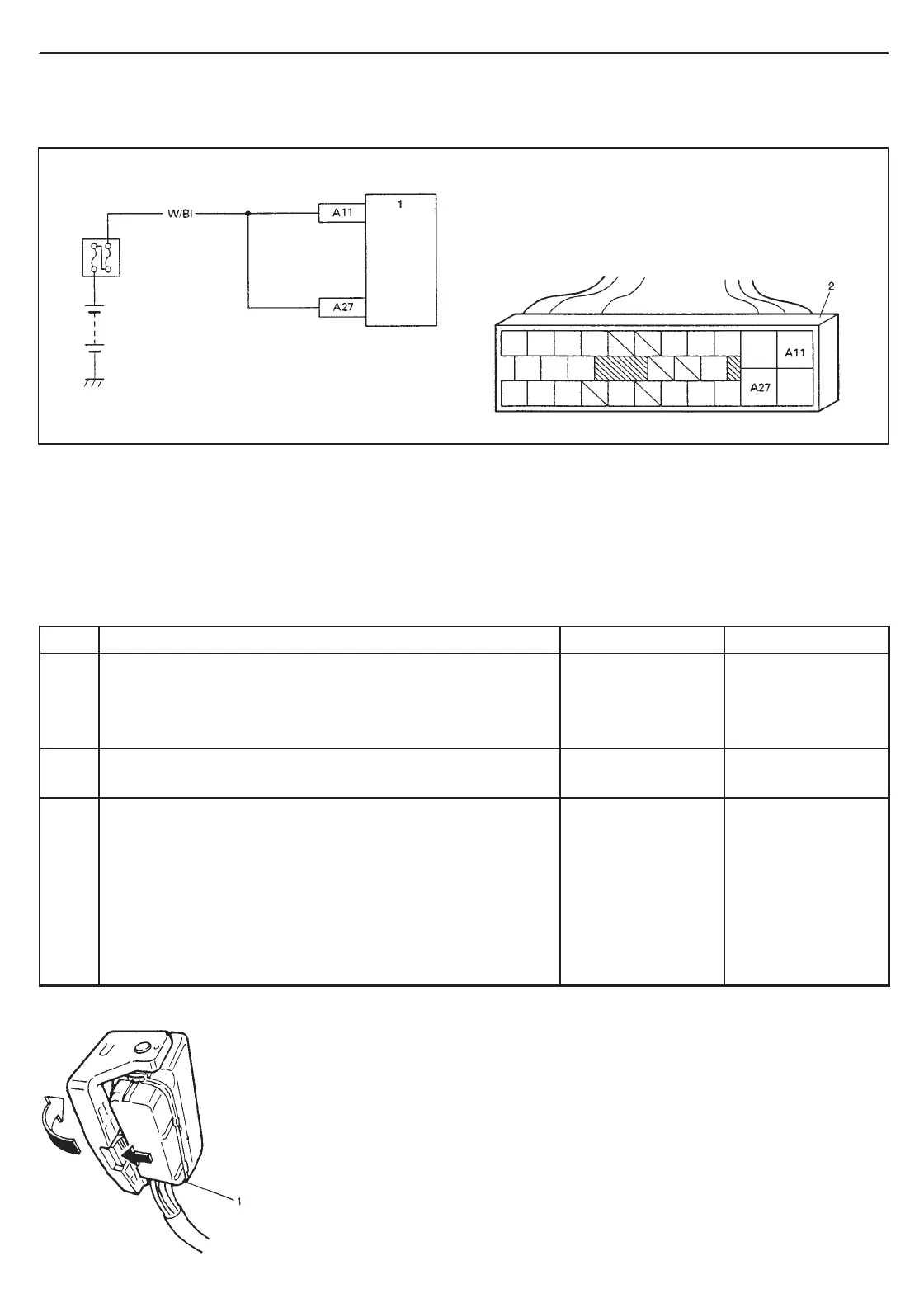
The ABS control module monitors the voltage at terminal ( “A11” and “A27”) of the fail-safe and pump motor relays
circuit constantly with the ignition switch turned ON. When all solenoid circuit voltages are below the specified value
or the voltage at the terminal “A27” became below the specified value while the pump motor is operating, this DTC
will be set. As soon as the voltage rises to the specified level, the set DTC will be cleared.
INSPECTION
STEP ACTION YES NO
1 Check battery voltage. Is it about 11 V or higher? Go to step 2. Check charging
system referring
to “CHARGING
SYSTEM” section.
2 Check ABS main fuse and connection. Is it in good
condition?
Go to step 3. Repair and/or
replace fuse.
3 1) Ignition switch OFF.
2) Disconnect ABS hydraulic unit/control module
connector. (See Fig. 1)
3) Check proper connection to ABS hydraulic unit/
control module connector at terminal “A27”.
4) If OK, then measure voltage between connector
terminal “A27” and body ground.
Is it 10 – 14 V?
Substitute a
known-good
ABS hydraulic
unit/control
module assembly
and recheck.
“W/Bl” circuit open.
Fig. 1
 Loading...

