YH4
GRAND
VITARA
8G-22 IMMOBILIZER CONTROL SYSTEM (IF EQUIPPED)
A8
12
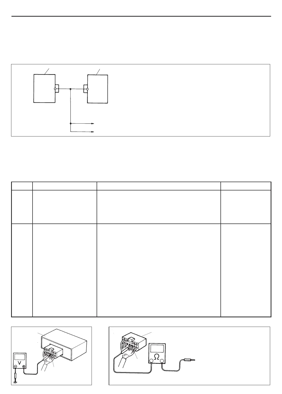
To SDM (if equipped with AIRBAG)
To data link connector (DLC)
1. Immobilizer Control Module
2. ECM/PCM
(j) (i)
(i)
(i)
DTC23 NO ECM/IMMOBILIZER CONTROL MODULE CODE TRANSMITTED
FROM ECM/PCM OR DLC CIRCUIT OPENED/SHORTED
DTC83 NO ECM/IMMOBILIZER CONTROL MODULE CODE TRANSMITTED
(P1621) FROM IMMOBILIZER CONTROL MODULE OR DLC CIRCUIT
OPENED/SHORTED
DESCRIPTION
When the ignition switch is ON, Immobilizer Control Module requests ECM/PCM and ECM/PCM requests Immobi-
lizer Control Module to transmit ECM/Immobilizer Control Module code. If ECM/Immobilizer Control Module code
is not transmitted from ECM/PCM or Immobilizer Control Module, Immobilizer Control Module sets DTC23 and
ECM/PCM sets DTC83 (P1621).
INSPECTION:
STEP ACTION YES NO
1 Check voltage between
Immobilizer Control Mod-
ule coupler terminal A8
and body ground with igni-
tion switch turned ON.
Is it 4 – 5V?
Go to Step 2. “(i)” or “(j)” wire
short.
2 1) Disconnect ECM/
PCM coupler with igni-
tion switch turned
OFF.
2) Is there continuity be-
tween Immobilizer
Control Module cou-
pler terminal A8 and
Data link connector
terminal of ECM/PCM
coupler? (For posi-
tions of Data link con-
nector terminal of
ECM/PCM coupler,
refer to Section 6E1 or
6E2.)
Poor A8 connection (Immobilizer Control Module) or
Poor Data link connector terminal connection (ECM/
PCM). If connections are OK, substitute a known-good
ECM/PCM or Immobilizer Control Module and re-
check.
NOTE :
After replacing with a known-good ECM/PCM,
register ECM/Immobilizer Control Module code
in ECM/PCM by performing procedure de-
scribed in “Procedure after ECM/PCM Replace-
ment” section.
After replacing with a known-good Immobilizer
Control Module, register ECM/Immobilizer Control
Module code in ECM/PCM and Transponder code
and ECM/Immobilizer Control Module code in Im-
mobilizer Control Module by performing proce-
dure described in “Procedure after Immobilizer
Control Module Replacement” section.
“(i)” or “(j)” wire be-
tween Immobilizer
Control Module and
ECM/PCM open.
Fig. 1 for step 1
1
A8
1. Immobilizer Control Module
1. Immobilizer Control Module coupler disconnected
1
A8
Connect to Data link connector terminal
of ECM/PCM coupler disconnected
Fig. 2 for step 2
 Loading...

