YH4
GRAND
VITARA
5E1-28 ANTILOCK BRAKE SYSTEM (ABS) (OPTIONAL)
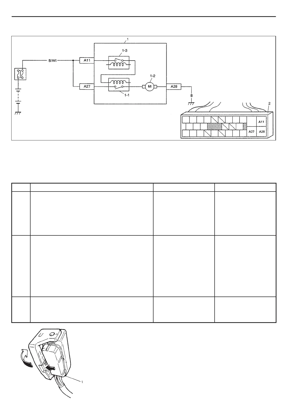
-1. ABS hydraulic unit/
control module assembly
1-1. ABS pump motor relay
1-2. ABS pump motor
1-3. ABS fail safe relay
-2. ABS hydraulic unit/
control module connector
of harness
1. ABS hydraulic
unit/ control
module connector
DTC 61 (DTC C1061) – ABS PUMP MOTOR CIRCUIT
DESCRIPTION
The ABS control module monitors the voltage at the monitor terminal of the pump motor circuit constantly with the
ignition switch turned ON. It sets this DTC when the voltage at the monitor terminal does not become high/low
according to ON/OFF commands to the motor relay of the module (does not follow these commands).
INSPECTION
STEP ACTION YES NO
1 1) Check pump motor referring to item
“ABS HYDRAULIC UNIT OPERATION
CHECK” in this section.
Is it in good condition?
Check terminals “A11”
and “A27” connection.
If connections OK,
substitute a known-
good ABS hydraulic
unit/control module
assembly and recheck.
Go to step 2.
2 1) Ignition switch OFF.
2) Disconnect ABS hydraulic unit/control
module connector. (See Fig. 1)
3) Check for proper connection to ABS
hydraulic unit/control module connector
at terminal “A27”.
4) If OK, then measure voltage between
terminal “A27” of module connector
and body ground.
Is it 10 – 14 V?
Go to step 3. “W/Bl” circuit open.
3 Measure resistance between connector
terminal “A28” of ABS hydraulic unit/control
module assembly.
Is it infinite ()?
“B” circuit open. Substitute a known-
good ABS hydraulic
unit/control module
assembly and recheck.
Fig. 1
 Loading...

