Toyota Orderpicker Model 7BPUE 15 Service Manual Section 7. Component Procedures
Control Handle
For replacement parts, refer to the parts
manual for the truck the handle is installed on.
Removal
1. Turn the key switch OFF and disconnect
the battery connector.
2.
Disconnect JPC9 and remove the Control
Handle from the truck.
N
OTE
:
Observe orientation of switches/
potentiometers and routing of
cables/wires as the handle is
Control Handle
N
OTE
:
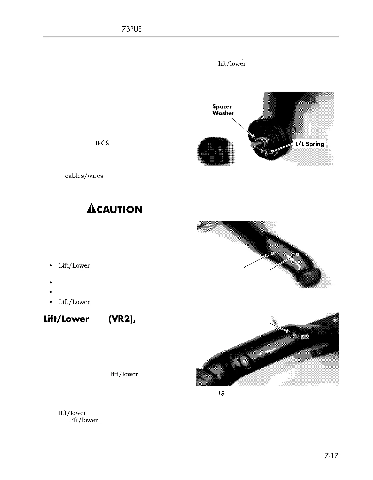
Carefully slide the two spacer washers,
lift/lower spring, and third spacer
washer off of the lift pot shaft. See
Figure 7
-
16.
Figure
7
-
16. Spacer Washer and
L/L
Spring Removal
disassembled to make reassembly
easier.
3.
Remove the three 3mm socket head cap
screws from the handle assembly. See
Be sure to observe proper precautions
against electrostatic discharge. See
"
Static Safety
"
on page
2
-
9.
Before disassembly, determine which
components require replacement:
Lift/Lower Potentiometer (Pot), Lift Spring,
and/or Horn Switch
Travel Pot and/or Gear
Travel Spring, Shaft Gear, and so on
Lift/Lower Knob
Lift/Lower Pot (VRZ), Lift Spring
and/or Horn Switch
Replacement
Disassembly
1. Remove the two 3/32 socket head nylon
set screws in the
lift/lower knob (thumb
lever). If stripped, use a small 1/8 in.
blade flat screwdriver and carefully back
out the set screw.
2.
Loosen the two metal set screws in the
lift/lower knob two full turns and remove
the
lift/lower knob.
Figures 7
-
17 and 7
-
18. Separate the cover
from the handle.
Figure
7
-
17. Cover Retaining Screws
-
Bottom
Figure
7
-
18.
Cover Retaining Screw
-
Top
N
OTE
:
Before sliding the pot bracket off the pot
shaft, identify which slot in the pot
bracket is used to hold the pot
anti
-
rotate tab. The anti
-
rotate tab
00700
-
CL222
-
05,
1
5 March 2005
 Loading...