Section 7. Component Procedures
Toyota Orderpicker Model
7BPUE 15 Service Manual
Steer Motor
Steer Motor
Electrical Components
9. Install new steer motor assembly on pivot
ring. Secure with four bolts and adhesive
(P/N
00590
-
04964
-
7 1). See Figure 7
-
6 1.
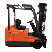
Inspection
Check brushes. Once brushes are removed,
check commutator. See Figure 7
-
60.
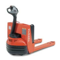
Figure 7
-
6
1.
Steer Motor Mounting
10.
Install steer switches.
11. Connect
M+
and M
-
to steer/tractor
Figure 7
-
60. Steer Motor Commutator, Brushes Removed
manager.
Replace
12. Install circuit card cover.
13. Connect power and test operation before
1. Turn key switch OFF and disconnect
returning truck to service.
battery.
2. Remove tractor covers. See
"
Tractor
Covers
"
on page 7
-
1 1.
3.
Remove circuit card cover.
4.
Disconnect wires M+ and M
-
from
steer/tractor manager.
5.
Remove proximity switches and
disconnect encoder.
6. Remove four mounting bolts and pull steer
motor assembly off pivot ring. See
Figure 7
-
6 1.
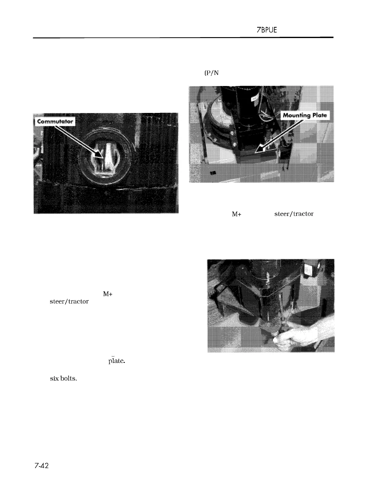
7. Remove six mounting bolts that secure
motor to mounting
Figure 7
-
62.
Separating Steer Motor from Gear Box
8.
Install mounting plate to steer motor using
six bolts.
Disassembly
1. Remove steer motor. See
"
Steer Motor
"
on
page 7
-
42.
2. Remove eight screws in the gear box. See
Figure 7
-
62.
3.
Replace parts as necessary. See
Figure 7
-
63.
00700
-
CL222
-
05,
1
5
March 2005
 Loading...