Toyota Orderpicker Model 7BPUE 15 Service Manual Section 7. Component Procedures
Control Handle
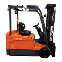
spring with the tangs straddling the pot pull the travel pot/bracket assembly from
bracket pin. See Figure 7
-
16.
the enclosure. See Figures 7
-
23 and 7
-
24.
N
O
T
E
:
Replace the spring if the tangs are not
parallel.
Do
not
bend the spring.
8.
Install the two remaining fiber washers.
9.
Install the lift/lower knob. See "Lift/Lower
Knob
Installation/Adjustment"
on
page 7
-
2
1.
Travel
Pot
(VR
1
)
Disassembly
1.
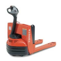
Remove the four hex head cap screws from
Figure 7
-
23. Travel Pot Bracket Screws
the front of the travel pot enclosure and
remove cover. See Figure 7
-
22.
Remove screws
Figure 7
-
24 Travel Pot Enclosure (Cover Removed)
Figure 7
-
22. Travel Pot Cover Removal
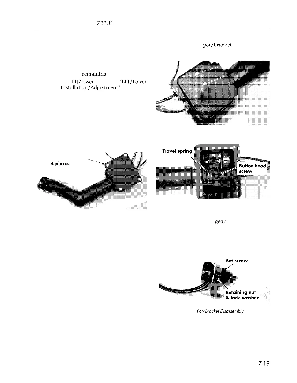
3.
Loosen the set screw on the gear two full
turns and slide the
gear off the shaft. See
-
2. Remove the two pan head machine screws Figure 7
-
25.
from the back of the enclosure. Carefully
4.
Remove retaining nut and lock washer
from pot and separate from the bracket.
See Figure 7
-
25.
Figure 7
-
25. Travel Pot/Bracket Disassembly
5. Carefully remove heat shrink tubing from
the terminals and identify the wires so
they can be installed in the same location
on the new pot.
00700
-
CL222
-
05,
1
5 March 2005
 Loading...