Section
6.
Codes and Tests
Toyota Orderpicker Model
7BPUE
15 Service Manual
Operator Display Messages
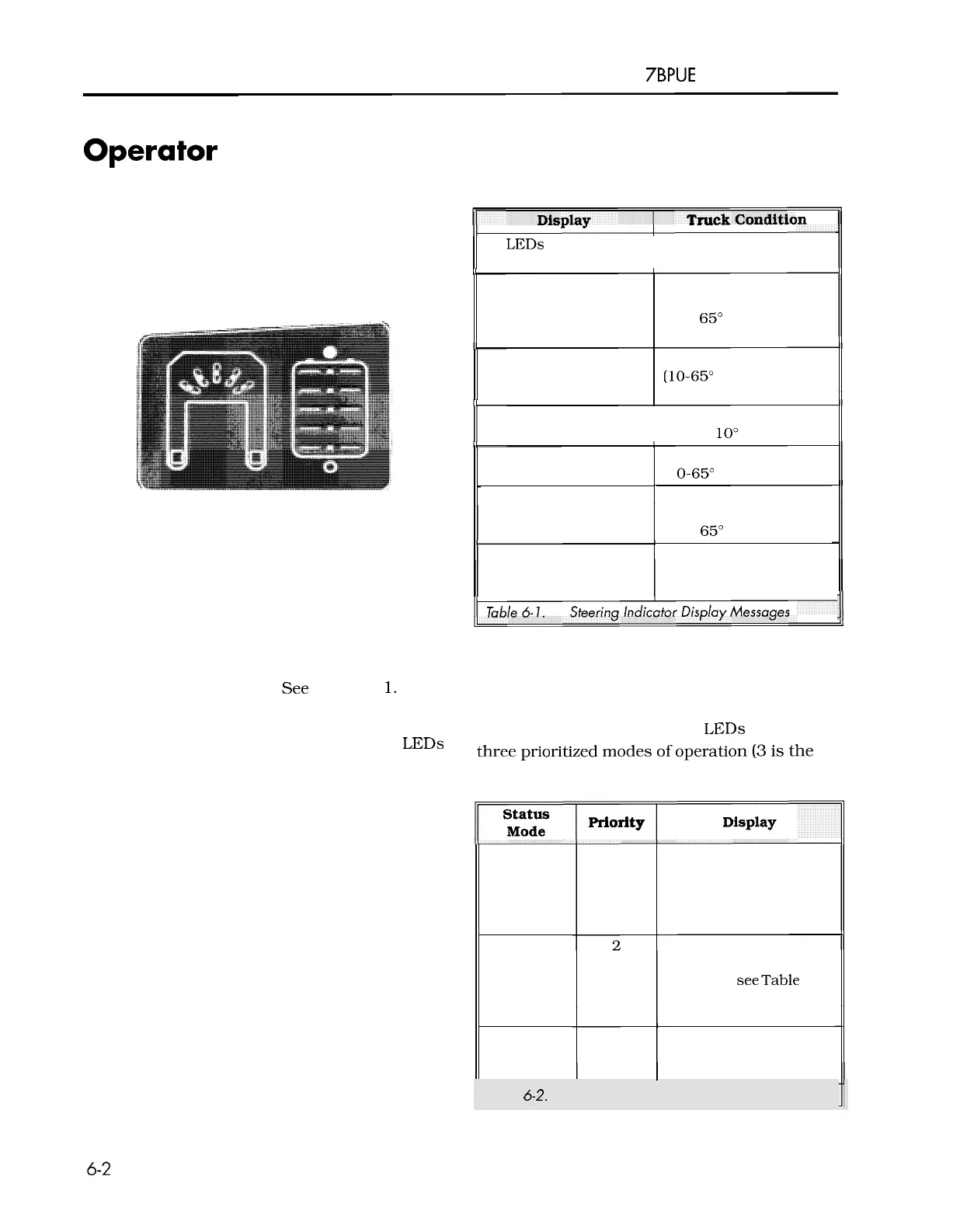
Operator Display
Table Each steering 6
-
1.
indicator message is explained in
Messages
The operator display has two sections, the
steering indicator and the battery indicator. See
Figure 6
-
1.
Steering Battery
Indicator Indicator
Figure
6
-
1.
Operator Display
Steering lndicator Messages
II
All LEDs scroll in
Drive unit position is
side-to-side pattern unknown
I1
Left LED on steady
Display
Drive unit in left,
end
-
of
-
travel zone (more
than
65"
counter -clockwise)
Truck
Condition
ll
Mid-Left LED on steady
Drive unit in left zone
(10-65"
counter-clockwise)
II
Center LED on steady
Drive unit in center zone
(within
10" of center)
Mid
-
Right LED on
steady
Right LED on steady
All LEDs blink in
unison as the horn
beeps
Drive unit in right zone
(1
0-65" clockwise)
Drive unit in right
end-of-travel zone (more
than
65" clockwise)
In maintenance mode
Table
6-
1.
Steering Indicator Display Messages
11
The steering indicator has five LEDs and shows
the current steering direction based on the
position of the drive unit.
See Figure 6
-
1.
Battery Indicator Messages
When the truck is in maintenance mode, the
The battery indicator has five
LEDs used in
steering indication is overridden, and the
LEDs
three prioritized modes
of
operation
(3
is the
flash as the horn
"
clicks
"
. See
"
Maintenance
highest priority).
Mode
"
on page 6
-
4.
Fault Code
Info
Display
Battery
State
-
of
-
Charge
Mode
3
(highest)
1
(lowest)
priority
Series of blinks for each
digit (all
5
blink
together); see
"
Operator
Display Fault Codes
"
on
page 6
-
15
Display
Blinks
a
single LED to
indicate a particular
condition;
seeTable 6
-
3,
"
Info Display Messages,
"
on page 6-3.
Single, steady LEDs
represent the current
I
state
-
of
-
charge.
I
Table
6-2.
Battery lndicator Messages
00700
-
CL222
-
05,
1
5
March 2005
 Loading...