Toyota Orderpicker Model 7BPUE 15 Service Manual Section 7. Component Procedures
Electrical Components
and label if necessary for proper
reinstallation. See Figure 7
-
7
1.
6.
Remove bus bars between contactors. See
Figure 7
-
70.
7.
Remove contactor coil wires
(X
and
Y)
by
pulling wire connector. Note their locations
and label if necessary.
8.
Remove contactor from mounting panel (2
hex nuts).
Install Assembly
1.
Position the contactor on the threaded
studs of the mounting panel and attach
with hex nuts. See Figure 7
-
7
1.
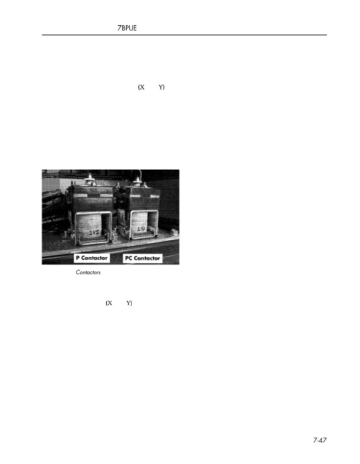
Figure
7
-
71.
Contactors
N
O
T
E
:
P contactor is intermittent duty; PC
contactor is continuous duty.
2. Attach coil wires
(X
and
Y)
by sliding
connector onto appropriate spade
terminal.
3.
Install bus bars on contactor lugs.
4.
Install fuses. Match location to
corresponding tractor frame label.
5.
Attach cables to appropriate lugs and
tighten securely.
6.
Connect power and test operation before
returning truck to service.
00700
-
CL222
-
05,
1
5 March 2005
Contactors
 Loading...