Toyota Orderpicker Model 7BPUE 15 Service Manual Section 7. Component Procedures
Drive and Brake
Brake
Figure 7
-
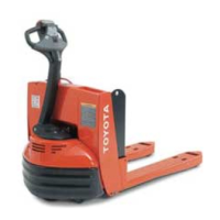
32. Brake Assembly,
installed
Removal
1. Turn key switch OFF and disconnect
battery.
2. Remove tractor covers.
Use extreme care whenever the truck
is
jacked up. Never block the truck
between the mast and the floor. Keep
hands and feet clear from vehicle while
jacking the truck. After the truck
is
jacked, place solid blocks beneath it to
support it. DO NOT rely on the jack
alone to support the truck. See
"
Jacking
Safety
"
on page
2
-
1
1.
3. Jack and block truck under tractor frame.
See
"
Tractor
"
on page 2
-
11.
4.
Disconnect electrical cable (PH5) to brake
assembly.
5. Cut cable ties and pull cables from
bracket. See Figure 7
-
32.
6.
Remove brake (3 screws). See Figure 7
-
32.
N
OTE
:
Note the location of the shims.
7. Remove brake release screws from tractor
(near steer motor) and install in brake.
Tighten screws until brake releases
completely.
Brake
Installation
1. Install brake assembly on drive motor.
2. Align cable bracket on brake assembly and
install bolts (3).
3. Connect PH5 and place cables in cable
bracket. Secure cable ties around cables.
4.
Remove blocks and test brake before
returning truck to service.
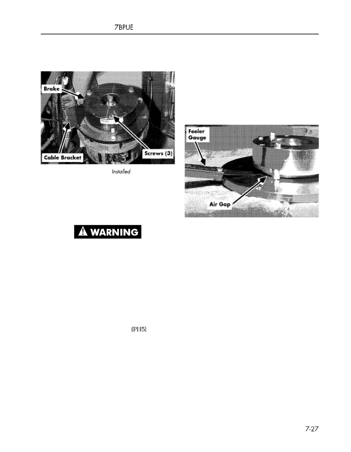
Figure 7
-
33. Measuring Brake Air Gap
Brake Air Gap Adjustment
During normal use, the friction plate will wear
(get thinner). This causes the air gap to
increase.
With the brake energized, measure the total air
gap with a feeler gauge. The total air gap should
be 0.010 to 0.015 inch (0.25
-
0.38 mm) and
uniform all the way around the armature disc.
A
total gap greater than 0.015 inch (0.38 mm)
indicates brake wear.
If
the air gap is too large, the brake may not
work properly; this is especially true when the
brake is hot or the battery charge level is low.
00700
-
CL222
-
05,
1
5 March 2005
 Loading...