Toyota Orderpicker Model 7BPUE 15 Service Manual Section 7. Component Procedures
Drive and Brake
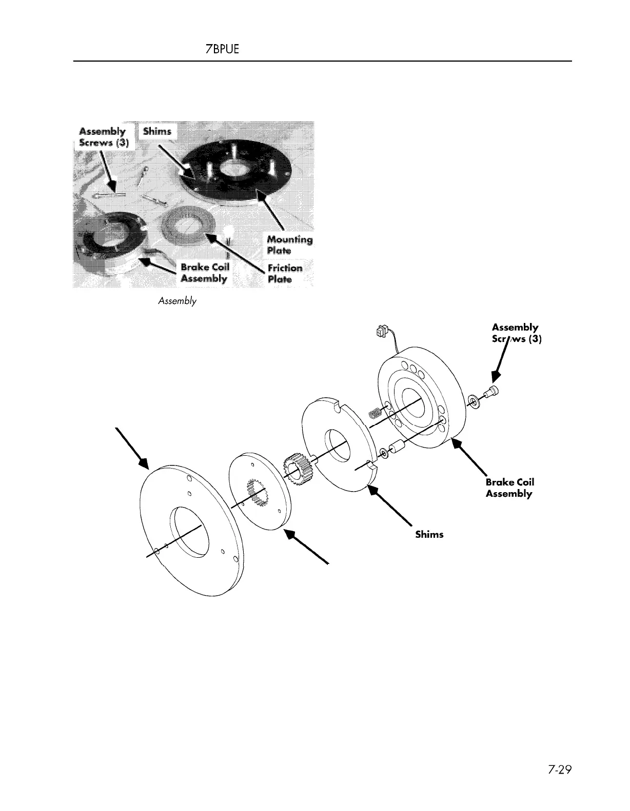
Assembly
Brake
1. Position new friction plate in center of
mounting plate. See Figure 7
-
36.
2. Install a 0.020 inch (0.508 mm) shim
between a 0.709 inch (18 mm) spacer and
mounting plate on each assembly screw.
See Figure 7
-
36.
3. Place brake coil assembly on top of friction
plate. See Figure 7
-
36.
4.
Tighten assembly screws (3). See
Figure 7
-
35.
5. Check the air gap. See
"
Brake Air Gap
Adjustment
"
on page 7
-
27.
Figure 7
-
36. Brake Assembly Components
Mounting
Plate
Friction
Plate
Figure 7
-
37: Brake Assembly, Detail View
00700
-
CL222
-
05,
1
5 March 2005
 Loading...