Toyota Orderpicker Model 7BPUE 15 Service Manual Section 7. Component Procedures
Hydraulic Components Lift Pressure Relief Valve Adjustment
Lift Pressure Relief Valve
required to lift maximum rated load
(value recorded earlier).
Adjustment
b.
TO
increase pressure, turn adjusting
screw
clockwise. To decrease pressure,
turn adjusting screw
counterclockwise.
c. Tighten locknut on lift pressure relief
valve.
9. Check pressure again. If value has
changed, repeat this procedure until the
correct pressure reading is obtained.
10. Turn key switch OFF.
1 1. Disconnect pressure gauge and reinstall
cap on lift pressure test port
(Gl).
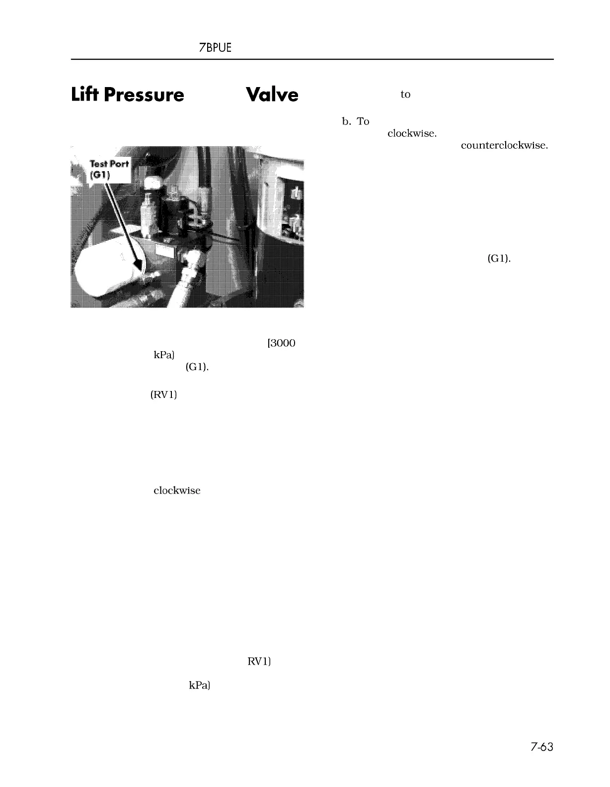
Figure
7
-
94.
Adjusting Lift Pressure
1. Install a calibrated pressure gauge [3000
psi (20,682 kPa) at mid
-
range] in the lift
pressure test port
(Gl). See Figure 7
-
94.
2. Loosen the locknut on the lift pressure
relief valve
(RV1) to back out the
high
-
pressure relief.
3.
Make sure emergency lower valve is
closed.
4. Place a maximum rated load
+
200 lb.
(90.7 kg.) on the forks.
5.
Start the lift system and turn the pressure
relief screw
clockwise until the platform
starts to lift. Note the pressure required
when the platform starts to elevate. On
three
-
stage trucks, continue lifting until
the third stage of the mast starts lifting.
Record the pressure reading.
6. Lower the operator platform and remove
the load.
7. Chain the mast sections together and lift
or lift the operator platform until the
upper limit is reached.
8.
To adjust pressure:
a. Continue trying to elevate, and turn lift
pressure adjusting screw (at
RV1) to
obtain a pressure reading of 100 to 300
psi (689 to 2068
kPa) greater than that
00700
-
CL222
-
05,
1
5 March 2005
 Loading...